R3 is floating what is the use of it?
Source Link
user1999
  • 1.5k
  • 5
  • 26
  • 36

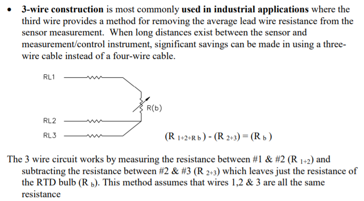
I can understand two or four wire connection for RTDs. But I don't get where they apply voltage or current and how they measure the resistor values for 3-wire connection:

enter image description here

Here is a page about these lead compensation techniques. In the 3 wire technique how are the resistors measured? In other words I want to see the current or voltage source connected to the three leads. Can someone illustrate how the source attached?

I'm asking how the current and voltage source are connected. The suggested duplicate doesn't show sort of thing explicitly. In short I dont get my answer when I read it. There is no current source there unlike in RTD.

Edit:

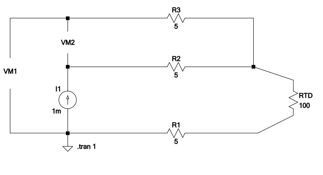
One of the answer suggested a circuit. I also found a similar one here.

enter image description here

But what Im stuck at is why is R3 necessary instead of a short? When I vary its value in simulation neither VM2 nor VM1 change at all. What is the function of R3 here? R3 is floating doesnt pass any current

I can understand two or four wire connection for RTDs. But I don't get where they apply voltage or current and how they measure the resistor values for 3-wire connection:

enter image description here

Here is a page about these lead compensation techniques. In the 3 wire technique how are the resistors measured? In other words I want to see the current or voltage source connected to the three leads. Can someone illustrate how the source attached?

I'm asking how the current and voltage source are connected. The suggested duplicate doesn't show sort of thing explicitly. In short I dont get my answer when I read it. There is no current source there unlike in RTD.

Edit:

One of the answer suggested a circuit. I also found a similar one here.

enter image description here

But what Im stuck at is why is R3 necessary instead of a short? When I vary its value in simulation neither VM2 nor VM1 change at all. What is the function of R3 here?

I can understand two or four wire connection for RTDs. But I don't get where they apply voltage or current and how they measure the resistor values for 3-wire connection:

enter image description here

Here is a page about these lead compensation techniques. In the 3 wire technique how are the resistors measured? In other words I want to see the current or voltage source connected to the three leads. Can someone illustrate how the source attached?

I'm asking how the current and voltage source are connected. The suggested duplicate doesn't show sort of thing explicitly. In short I dont get my answer when I read it. There is no current source there unlike in RTD.

Edit:

One of the answer suggested a circuit. I also found a similar one here.

enter image description here

But what Im stuck at is why is R3 necessary instead of a short? When I vary its value in simulation neither VM2 nor VM1 change at all. What is the function of R3 here? R3 is floating doesnt pass any current
Post Closed as "Duplicate" by Andy aka, Dave Tweed
added 367 characters in body
Source Link
user1999
  • 1.5k
  • 5
  • 26
  • 36

I can understand two or four wire connection for RTDs. But I don't get where they apply voltage or current and how they measure the resistor values for 3-wire connection:

enter image description here

Here is a page about these lead compensation techniques. In the 3 wire technique how are the resistors measured? In other words I want to see the current or voltage source connected to the three leads. Can someone illustrate how the source attached?

I'm asking how the current and voltage source are connected. The suggested duplicate doesn't show sort of thing explicitly. In short I dont get my answer when I read it. There is no current source there unlike in RTD.

Edit:

One of the answer suggested a circuit. I also found a similar one here.

enter image description here

But what Im stuck at is why is R3 necessary instead of a short? When I vary its value in simulation neither VM2 nor VM1 change at all. What is the function of R3 here?

I can understand two or four wire connection for RTDs. But I don't get where they apply voltage or current and how they measure the resistor values for 3-wire connection:

enter image description here

Here is a page about these lead compensation techniques. In the 3 wire technique how are the resistors measured? In other words I want to see the current or voltage source connected to the three leads. Can someone illustrate how the source attached?

I'm asking how the current and voltage source are connected. The suggested duplicate doesn't show sort of thing explicitly. In short I dont get my answer when I read it. There is no current source there unlike in RTD.

Edit:

One of the answer suggested a circuit. I also found a similar one here.

enter image description here

But what Im stuck at is why is R3 necessary instead of a short? When I vary its value in simulation neither VM2 nor VM1 change at all. What is the function of R3 here?

added 171 characters in body
Source Link
user1999
  • 1.5k
  • 5
  • 26
  • 36

I can understand two or four wire connection for RTDs. But I don't get where they apply voltage or current and how they measure the resistor values for 3-wire connection:

enter image description here

Here is a page about these lead compensation techniques. In the 3 wire technique how are the resistors measured? In other words I want to see the current or voltage source connected to the three leads. Can someone illustrate how the source attached?

I'm asking how the current and voltage source are connected. The suggested duplicate doesn't show sort of thing explicitly. In short I dont get my answer when I read it. There is no current source there unlike in RTD.

I can understand two or four wire connection for RTDs. But I don't get where they apply voltage or current and how they measure the resistor values for 3-wire connection:

enter image description here

Here is a page about these lead compensation techniques. In the 3 wire technique how are the resistors measured? In other words I want to see the current or voltage source connected to the three leads. Can someone illustrate how the source attached?

I'm asking how the current and voltage source are connected. The suggested duplicate doesn't show sort of thing explicitly. In short I dont get my answer when I read it. There is no current source there unlike in RTD.

Source Link
user1999
  • 1.5k
  • 5
  • 26
  • 36
Loading