added 448 characters in body
Source Link
hacktastical
  • 58.4k
  • 2
  • 54
  • 166

The request is to see if the motor is plugged in or not, yes?

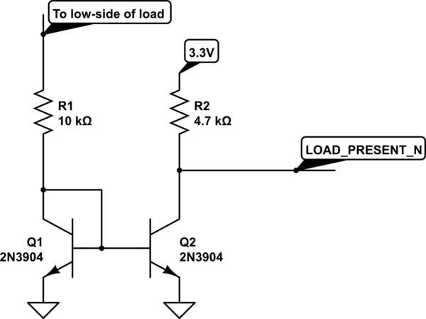
I faced a similar problem for a product, to detect if a display panel was plugged in. My solution? Use a current mirror to pass a small sensing current into the load, like so:
schematic

simulate this circuit – Schematic created using CircuitLab

Q1 sinks a small current from the connected load, turning on Q2 and bringing signal LOAD_PRESENT_N low. If there is no load connected, Q1 and Q2 will be off, so LOAD_PRESENT_N will be high.

Ideally you want to use a matched pair for Q1/Q2, but for this kind of basic use separate NPNs should be ok.

EDIT: add to the above: a weak pull-up to the load (+) side to complete the low-current sense circuit. The sensing would only be used when the motor is idle, such as during initial power on or during a diag self-test.

Also note that the sensing connections are to the motor, not to the Rsense on the H-bridge low side. You still need Rsense for the error amplifier, and it should be a low value (like 0.1 ohm or so) to minimize power loss.

The request is to see if the motor is plugged in or not, yes?

I faced a similar problem for a product, to detect if a display panel was plugged in. My solution? Use a current mirror to pass a small sensing current into the load, like so:

schematic

simulate this circuit – Schematic created using CircuitLab

Q1 sinks a small current from the connected load, turning on Q2 and bringing signal LOAD_PRESENT_N low. If there is no load connected, Q1 and Q2 will be off, so LOAD_PRESENT_N will be high.

Ideally you want to use a matched pair for Q1/Q2, but for this kind of basic use separate NPNs should be ok.

EDIT: add to the above: a weak pull-up to the load (+) side to complete the low-current sense circuit. The sensing would only be used when the motor is idle, such as during initial power on or during a diag self-test.

Also note that the sensing connections are to the motor, not to the Rsense on the H-bridge low side. You still need Rsense for the error amplifier, and it should be a low value (like 0.1 ohm or so) to minimize power loss.

Source Link
hacktastical
  • 58.4k
  • 2
  • 54
  • 166

The request is to see if the motor is plugged in or not, yes?

I faced a similar problem for a product, to detect if a display panel was plugged in. My solution? Use a current mirror to pass a small sensing current into the load, like so:

schematic

simulate this circuit – Schematic created using CircuitLab

Q1 sinks a small current from the connected load, turning on Q2 and bringing signal LOAD_PRESENT_N low. If there is no load connected, Q1 and Q2 will be off, so LOAD_PRESENT_N will be high.

Ideally you want to use a matched pair for Q1/Q2, but for this kind of basic use separate NPNs should be ok.