added 905 characters in body
Source Link
Anonymous
  • 7.2k
  • 1
  • 17
  • 46

I have two versions of the input signal:

  • 5V inactive level, 3.2V active;
  • 5V inactive level, 0V active level.

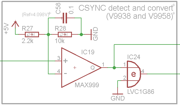
Thinking on making universal circuit to support both signals, I decided to use comparator, having threshold voltage at about 4V. Here's the circuit:

enter image description here

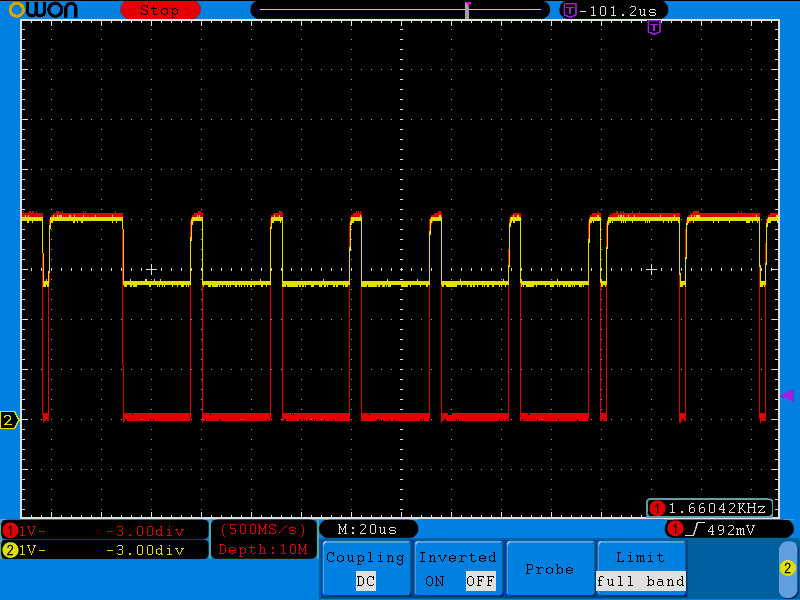
I built a prototype, and it shows unexpected (for me) behavior:

enter image description here

Red is voltage on positive input pin, yellow is on negative. Capacitor C58 was removed.

Searching through internet I found this question. It is about operational amplifier, and not about comparator. But I took a closer look into the datasheet, and found the following:

Differential Input Clamp Voltage --- VCC = 5.5V, VIN- = 0V, IIN+ = 100µA --- 2.1 V

Is it the information I should be looking at? Does it mean that voltage between + and - inputs must be not larger than 2.1 V, otherwise there will be current path between the inputs? Is it naive to assume that if I have comparator powered from 5V, that it must be able to properly handle differential voltages on the whole power scale? And why datasheet does not state that there's such a limitation in its headline?

Update:

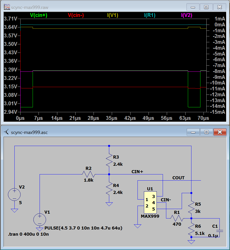
After considering answers below I decided to stick with MAX999 so far, and designed the following circuit:

enter image description here

I still think it is an overkill, but at least it is expected to work properly:

  • supply current is about 8 mA. In my previous simulations MAX999 model was failing when IN+ was approaching IN- starting consuming about 60 mA, most probably because of issues in definition of the input stage circuitry.
  • digital input was resized and re-leveled (green), with reference voltage placed into the exact center of the worst case for the input signal;
  • circuit draws less than 1 mA from the positive input, and almost nothing through the negative input;
  • power on current is much less than 10 mA, limited by the 470 Ohm resistor;
  • differential voltage does never go out of 2.1 V range.

I have two versions of the input signal:

  • 5V inactive level, 3.2V active;
  • 5V inactive level, 0V active level.

Thinking on making universal circuit to support both signals, I decided to use comparator, having threshold voltage at about 4V. Here's the circuit:

enter image description here

I built a prototype, and it shows unexpected (for me) behavior:

enter image description here

Red is voltage on positive input pin, yellow is on negative. Capacitor C58 was removed.

Searching through internet I found this question. It is about operational amplifier, and not about comparator. But I took a closer look into the datasheet, and found the following:

Differential Input Clamp Voltage --- VCC = 5.5V, VIN- = 0V, IIN+ = 100µA --- 2.1 V

Is it the information I should be looking at? Does it mean that voltage between + and - inputs must be not larger than 2.1 V, otherwise there will be current path between the inputs? Is it naive to assume that if I have comparator powered from 5V, that it must be able to properly handle differential voltages on the whole power scale? And why datasheet does not state that there's such a limitation in its headline?

Update:

After considering answers below I decided to stick with MAX999 so far, and designed the following circuit:

enter image description here

I still think it is an overkill, but at least it is expected to work properly:

  • supply current is about 8 mA. In my previous simulations MAX999 model was failing when IN+ was approaching IN- starting consuming about 60 mA, most probably because of issues in definition of the input stage circuitry.
  • digital input was resized and re-leveled (green), with reference voltage placed into the exact center of the worst case for the input signal;
  • circuit draws less than 1 mA from the positive input, and almost nothing through the negative input;
  • power on current is much less than 10 mA, limited by the 470 Ohm resistor;
  • differential voltage does never go out of 2.1 V range.
Source Link
Anonymous
  • 7.2k
  • 1
  • 17
  • 46

MAX999 draws current through negative input

I have two versions of the input signal:

  • 5V inactive level, 3.2V active;
  • 5V inactive level, 0V active level.

Thinking on making universal circuit to support both signals, I decided to use comparator, having threshold voltage at about 4V. Here's the circuit:

enter image description here

I built a prototype, and it shows unexpected (for me) behavior:

enter image description here

Red is voltage on positive input pin, yellow is on negative. Capacitor C58 was removed.

Searching through internet I found this question. It is about operational amplifier, and not about comparator. But I took a closer look into the datasheet, and found the following:

Differential Input Clamp Voltage --- VCC = 5.5V, VIN- = 0V, IIN+ = 100µA --- 2.1 V

Is it the information I should be looking at? Does it mean that voltage between + and - inputs must be not larger than 2.1 V, otherwise there will be current path between the inputs? Is it naive to assume that if I have comparator powered from 5V, that it must be able to properly handle differential voltages on the whole power scale? And why datasheet does not state that there's such a limitation in its headline?