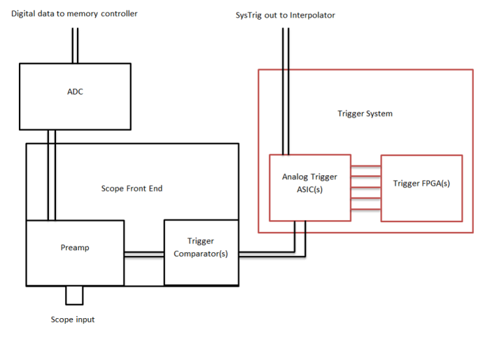
While basic USB oscilloscopes use continuous software\digital triggering, this is not how benchtop scopes work. There is too much analog bandwidth at high speeds to be able to monitor all the information with an ADC. Especially since modern scopes have advanced triggering options.
Modern oscilloscopes have comparators that compare the voltage coming in to a preset level, then trigger on that. At high speeds, the ADC can keep up with the data, but processing it becomes an issue, so when triggered the scope only shows the ADC data around the trigger point.
 Source: Keysight
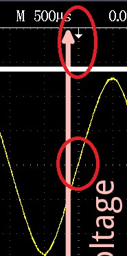
Sometimes the voltage at the origin is not equal to the trigger level, and the signal even drifts slowly to either direction. What causes the signal to drift even if the trigger is set?
The little arrow determines where the scope's trigger level is triggering at.
Another confusion that I have: I've seen the right side of the origin called the "post-trigger" data and the left side "pre-trigger" data. How is there data from before the trigger, if data gathering starts from the trigger? Shouldn't the trigger point actually be at the very left of the screen?
The ADC is rollingIf you use the horizontal position button you can move the trigger point to the left and get more data to the right. Because most people are interested in what happens before the trigger, oscilloscopes show that also.

