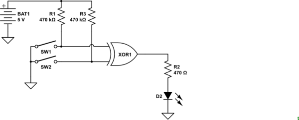
simulate this circuit – Schematic created using CircuitLab
70I am trying to make a circuit in which the switches will determine the outputs for the xor gate however when i used the switches it is giving me the opposite outputs. For example, a 1 & 1 should give a 0 but i am getting an output of 1.
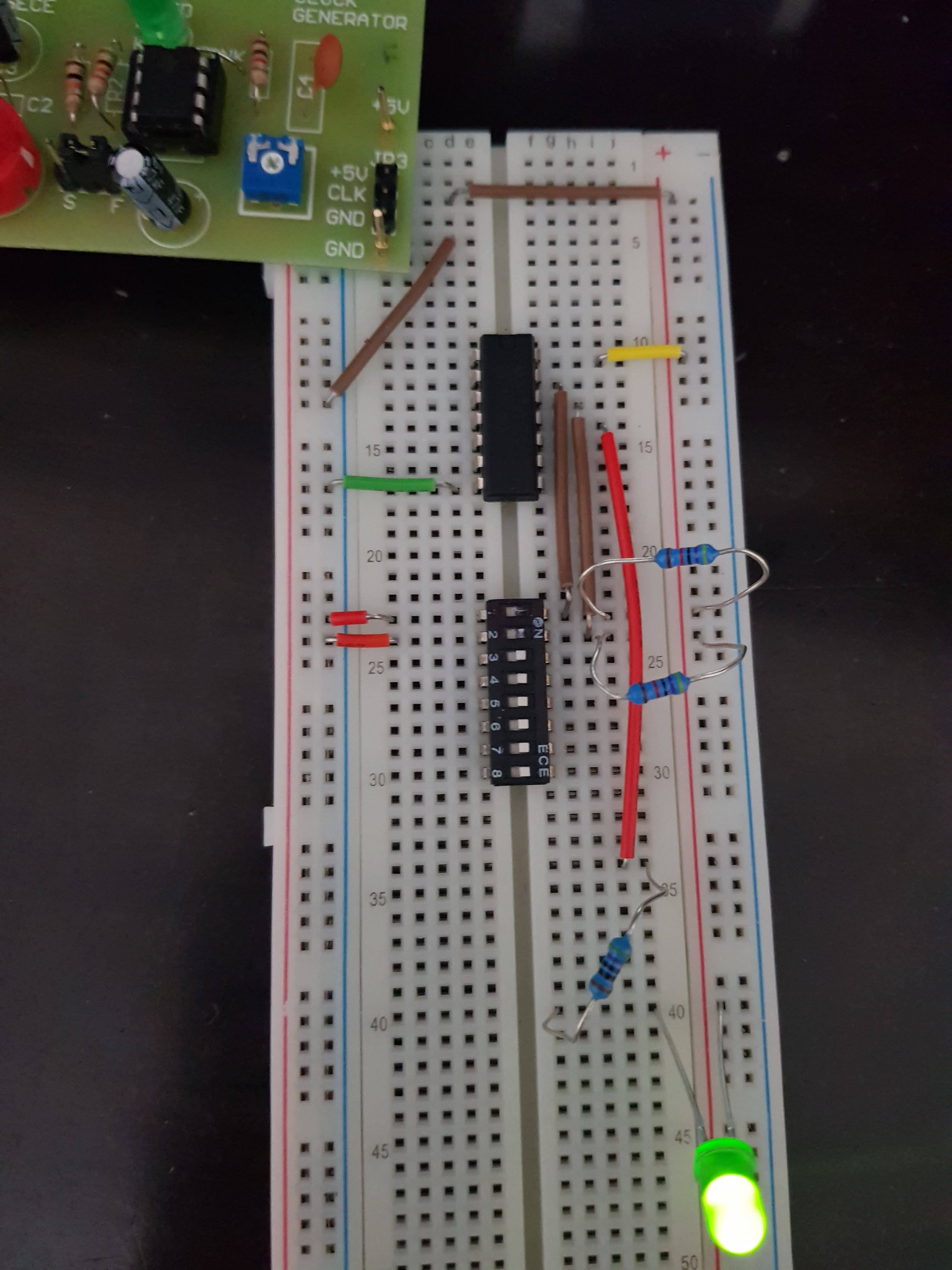
I have attached a picture of my board.
Note the resistors connected to 5v and to switch are 470kohm and the resistor connected to led is 470 omhs.
note that for IC the VCC is on top right and grnd is on the bottom left. Also the top two pins from right after VCC are the inputs and the one below that is the output (HC86 gate).
Edit * I am not sure the schematic is correct as I was not given one to work with but I think this is essentially what I am trying to do.

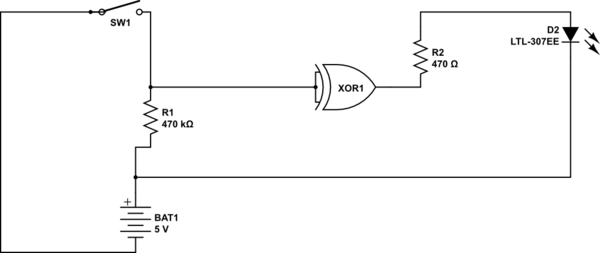
Figure 3. Corrected schematic for OP to verify. [By @Transistor.]


