The junction“junction to ambientambient” thermal resistance is equivalent to a resistance parallel to the junction“junction to soldersolder” thermal resistance and, that parallel resistance is usually much greater than the junction“junction to soldersolder” resistance and can be usually ignored.
So, if you want to prevent your device from overheating, you need to have copper area of some significance around the LED solder pads. The copper area will have a thermal resistance to ambient and that then becomes in series with the junction to solder resistance: -
Total thermal resistance is therefore: -
\$R_{(JUNCTION-SOLDER)} + R_{(CU-AMBIENT)}\$.
You thereforethen have to calculate what size copper provides a low enough thermal resistance to prevent your LEDs from overheating when they are dissipating 3 watts. Be also aware that the local ambient temperature around the circuit board will rise as heat is passed to it. By how much is dependent on other factors like forced air cooling or the use of a metal case.
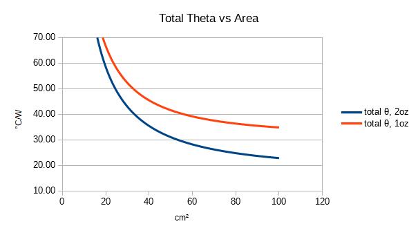
However, there is a good site that will provide useful insights into how big the copper area needs to be and here's a graph that is useful: -
So, if you can get away with your copper to ambient thermal resistance being 40 °C per watt, then about 60 square cm of 1 oz copper is required. I have a feeling that with a total power of 30 watts you will need something substantial.

