Rather than look up some boilerplate circuits and not understanding how they work, try designing from fundamental principles and building up from there. It sounds like you want some voltage controlled current which can drive 0-250mA through a 0-40 Ohm load - not an unreasonable task. Keep in mind the functionality of an op-amp (approximately):
Inputs take no current
Output of op-amp limited to Vpower+ and Vpower- (for rail to rail OPA)
When there is a negative feedback path, OPA tries to keep V+ = V-
A very simple current source according to these rules can be derived:

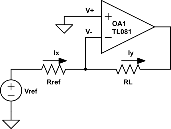
simulate this circuit – Schematic created using CircuitLab
In the above circuit, V+ is grounded (e.g. 0 V). Because the OPA is in negative feedback via the load resistor (RL), rule #3 tells us V- = V+ = 0V. The current Ix = (Vref-0)/Rref via Ohm's law. Rule #1 tells us that the inputs of the OPA take no current, therefore Iy = Ix via KCL. We can conclude that the above circuit is a current source where the current through the load RL, Iy = Vref/Rref. Note the current doesn't depend on the value of the load resistor RL, making it a current source.
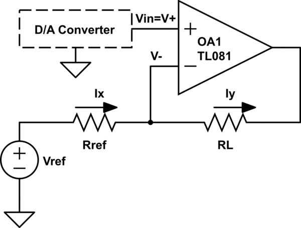
Now your first intuition might be to take this circuit and replace Vref with a DAC. Although this might work, most likely the DAC cannot supply enough current directly (e.g. the output impedance of the DAC is not negligible). However, from the analysis above, we can see another way to control the current, through V+, which in the above circuit is simply grounded. Modifying the above circuit this way yields:

We've replaced the V+ network (which was just a connection to ground before) with the D/A converter (Vin). Therefore, Vin = V+ and furthermore, because V+ is an OPA input, it draws no current so pretty much any DAC should suffice. How does this change the equations? Recall current Ix = (Vref-0)/Rref in the first circuit. The change means now Ix = (Vref-Vin)/Rref. The same applies for Iy, therefore your load current is Iy = (Vref-Vin)/Rref. Note that you can choose appropriate fixed values for your application for Vref and Rref, e.g. if Vin = 0 and you want the output to be 250mA, then you can fix Vref = 10V, Rref = 40 Ohm. Then you can vary Vin to adjust the output current. E.g. with the above configuration, Vin = 5V will yield 125mA, etc. Obviously Vin has an inverse relationship with the current, but it sounds like Vin is coming from some microcontroller/digital source, so that shouldn't be a problem.
Note that there is an additional issue of what the op-amp power needs to be (e.g. +/- 12, or +/- 15, etc). This depends on your maximum load resistance, as the limiting factor is how high or low the output of the OPA can go. If you understand the analysis I've given you, you should be able to go ahead and solve for that given your specifications. As a hint, you will need to apply rule #2 of OPAs.
The Howland current source has an additional constraint that the feedback resistor is fixed, rather than the feedback resistor being the load itself. Nothing in your problem description suggests that you need or want this, though I suppose some OPAs may require this.
