Fixed shouting, random capitalisation, typos, spelling, and grammar. Some issue may still remain.
Source Link

IGBT EMITTER COLLECTOR SPIKE OVERSHOOTemitter collector spike overshoot


I am building a step up transformer for an output of 100 kV, 50 mA, at 50 kHz.

schematic

simulate this circuit – Schematic created using CircuitLab

So, I am building a STEP UP transformer for output Volt 100 Kilo Volt,50 ma Output,50 Kilo Hertz Frequency.ForFor that iI have planplanned to use Halfa half bridge circuit with Ferrite Transformera ferrite transformer. However to test the circuit iI am putting 30 volt dc V DC across HALF BRIDGEa half bridge input. I am using a TLP350 as a Gate driver. I am using 10 Ohm Resistor Ω resistor as a Gate Turn Ongate turn on resistance.And, and a 1N5822 as Turn Offa turn off diode for gate driver. enter image description here
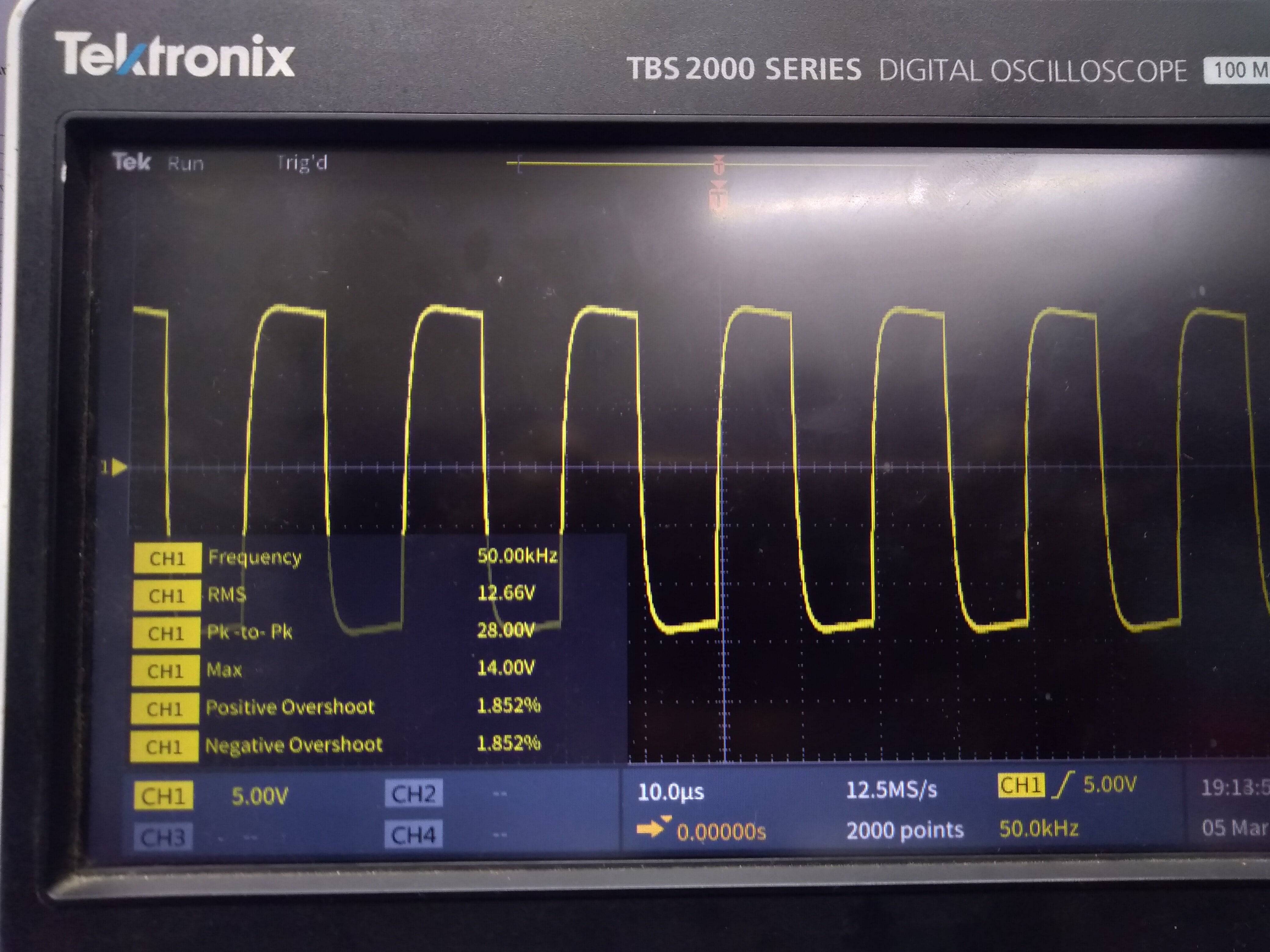
Lower side IGBT gate voltage

This is my Lower Sidelower side IGBT gate VOLTAGE voltage,Probe the probe directly connected at IGBT Legslegs. 15 VOLT V.Probe The probe is in 10X Modemode...

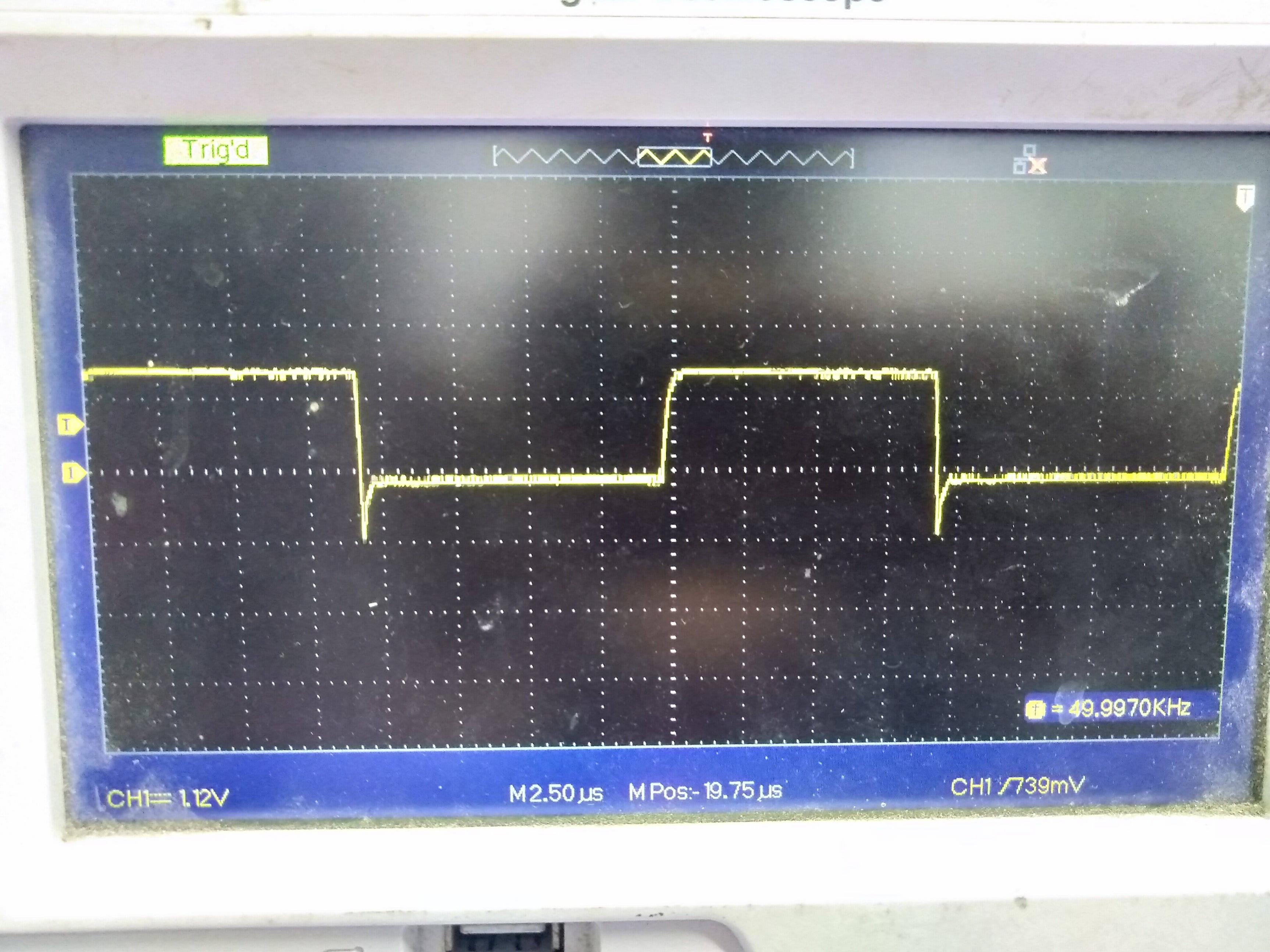
enter image description hereHalf bridge output

This is my Half Bridge Output half bridge output,Load load is a 60 Watt 12 Volt CAR HEADLIGHTcar headlight. enter image description here
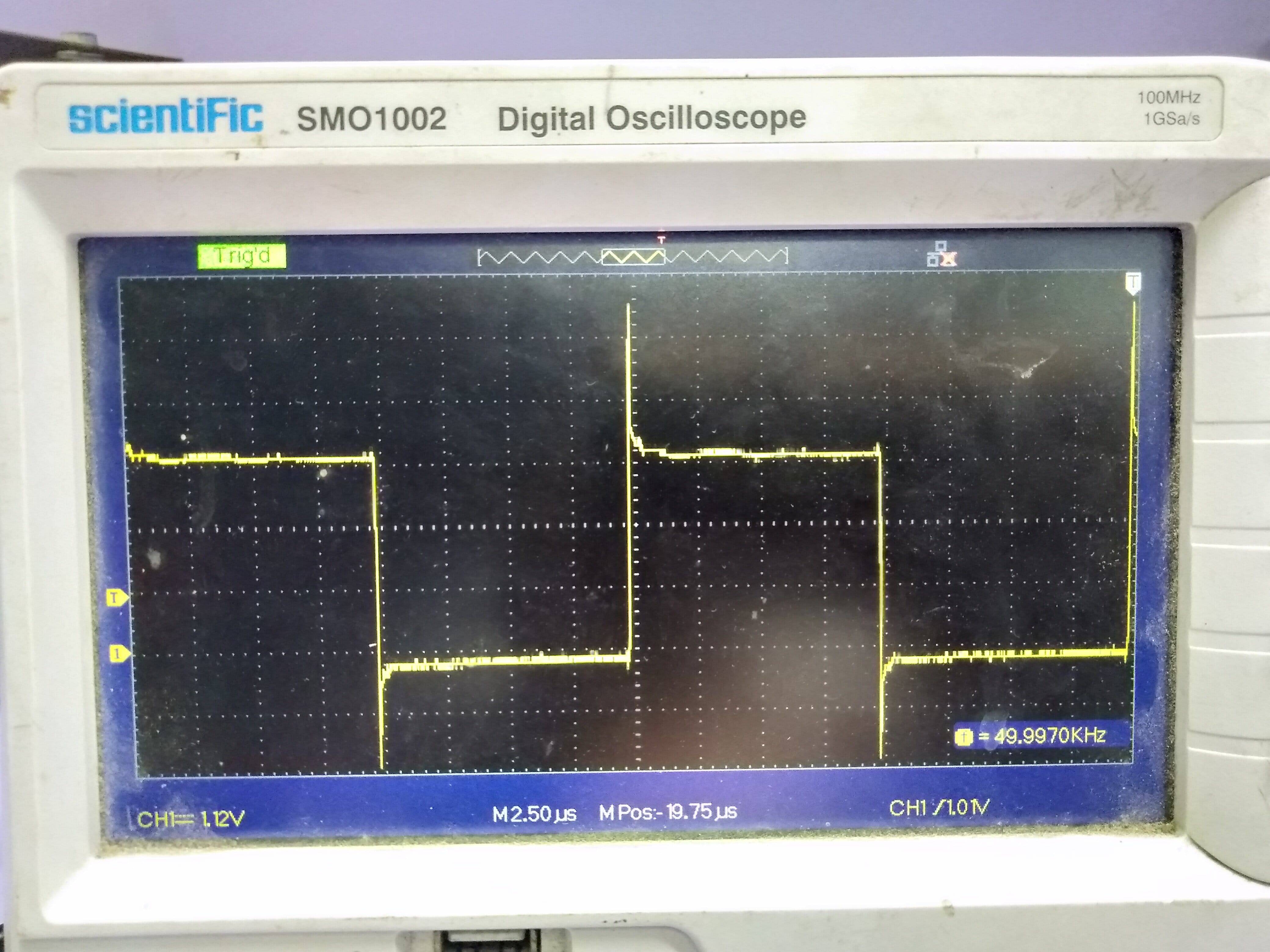
Voltage spike/overshoot at the leg of lower side IGBT

This is my ISSUEissue, Volatgea voltage spike/Overshootovershoot at the leg OF lOWER SIDE igbt.of lower side IGBT. Probe is connected in emitter and Collectorcollector pin.Collector Collector pin referenced to Emitteremitter. This waveform taken without the snubbere Circuits.snubber circuits.

My question is how iI can reduce the spike at IGBT Collector Emitterthe IGBT's collector emitter pin ???enter image description here
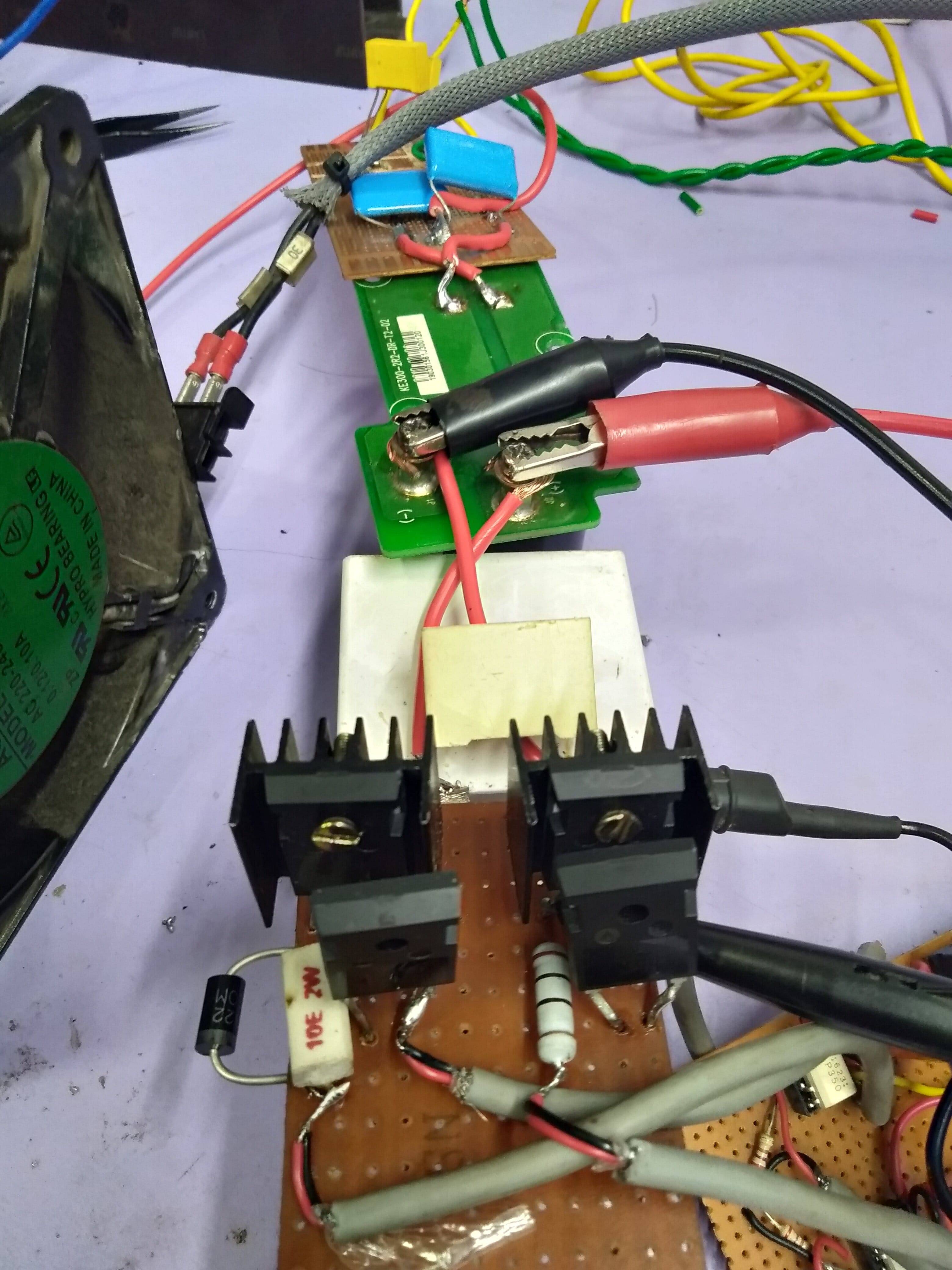
Test setup

This is my Test Setuptest setup for now. I have a 2uf2 µf,2kv 2 kV snubber cap close to Half bridfe IGBT'Shalf bridge IGBTs. 10 KILO OHM kΩ resistor connected in gate and emitter at both igbtIGBT to reduce accidental turn on. I am using IHW40N65R5 IGBT with DSEI60-12A Diodediode with Eacheach IGBT.. enter image description here
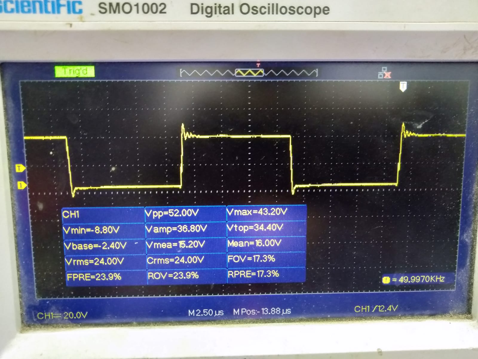
Lower side IGBT collector emitter voltage with snubber

After iI put the snubber circuit My Lowermy lower side igbt collectroIGBT collector emitter voltage look like this,Spike spike reduced but little ringing happening now... Is that ok ?? Can iI power up my circuit upto High Voltup to high voltage DC  ? likeLike 300 Volt DC..?

IGBT EMITTER COLLECTOR SPIKE OVERSHOOT


schematic

simulate this circuit – Schematic created using CircuitLab

So, I am building a STEP UP transformer for output Volt 100 Kilo Volt,50 ma Output,50 Kilo Hertz Frequency.For that i have plan to use Half bridge circuit with Ferrite Transformer. However to test the circuit i am putting 30 volt dc across HALF BRIDGE input. I am using TLP350 as a Gate driver. I am using 10 Ohm Resistor as a Gate Turn On resistance.And 1N5822 as Turn Off diode for gate driver. enter image description here

This is my Lower Side IGBT gate VOLTAGE ,Probe directly connected at IGBT Legs. 15 VOLT.Probe is in 10X Mode...

enter image description here

This is my Half Bridge Output ,Load is a 60 Watt 12 Volt CAR HEADLIGHT. enter image description here

This is my ISSUE, Volatge spike/Overshoot at the leg OF lOWER SIDE igbt.. Probe is connected in emitter and Collector pin.Collector pin referenced to Emitter This waveform taken without the snubbere Circuits..

My question is how i can reduce the spike at IGBT Collector Emitter pin ???enter image description here

This is my Test Setup for now. I have a 2uf,2kv snubber cap close to Half bridfe IGBT'S. 10 KILO OHM resistor connected in gate and emitter at both igbt to reduce accidental turn on. I am using IHW40N65R5 IGBT with DSEI60-12A Diode with Each IGBT.. enter image description here

After i put the snubber circuit My Lower side igbt collectro emitter voltage look like this,Spike reduced but little ringing happening now... Is that ok ?? Can i power up my circuit upto High Volt DC  ? like 300 Volt DC..

IGBT emitter collector spike overshoot

I am building a step up transformer for an output of 100 kV, 50 mA, at 50 kHz.

schematic

simulate this circuit – Schematic created using CircuitLab

For that I have planned to use a half bridge circuit with a ferrite transformer. However to test the circuit I am putting 30 V DC across a half bridge input. I am using a TLP350 as a Gate driver. I am using 10 Ω resistor as a gate turn on resistance, and a 1N5822 as a turn off diode for gate driver.

Lower side IGBT gate voltage

This is my lower side IGBT gate voltage, the probe directly connected at IGBT legs. 15 V. The probe is in 10X mode...

Half bridge output

This is my half bridge output, load is a 60 Watt 12 Volt car headlight.

Voltage spike/overshoot at the leg of lower side IGBT

This is my issue, a voltage spike/overshoot at the leg of lower side IGBT. Probe is connected in emitter and collector pin. Collector pin referenced to emitter. This waveform taken without the snubber circuits.

My question is how I can reduce the spike at the IGBT's collector emitter pin?

Test setup

This is my test setup for now. I have a 2 µf, 2 kV snubber cap close to half bridge IGBTs. 10 kΩ resistor connected in gate and emitter at both IGBT to reduce accidental turn on. I am using IHW40N65R5 IGBT with DSEI60-12A diode with each IGBT.

Lower side IGBT collector emitter voltage with snubber

After I put the snubber circuit my lower side IGBT collector emitter voltage look like this, spike reduced but little ringing happening now... Is that ok? Can I power up my circuit up to high voltage DC? Like 300 Volt DC?

added 662 characters in body
Source Link

schematic

simulate this circuit – Schematic created using CircuitLab

So, I am building a STEP UP transformer for output Volt 100 Kilo Volt,50 ma Output,50 Kilo Hertz Frequency.For that i have plan to use Half bridge circuit with Ferrite Transformer. However to test the circuit i am putting 30 volt dc across HALF BRIDGE input. I am using TLP350 as a Gate driver. I am using 10 Ohm Resistor as a Gate Turn On resistance.And 1N5822 as Turn Off diode for gate driver. enter image description here

This is my Lower Side IGBT gate VOLTAGE ,Probe directly connected at IGBT Legs. 15 VOLT.Probe is in 10X Mode...

enter image description here

This is my Half Bridge Output ,Load is a 60 Watt 12 Volt CAR HEADLIGHT. enter image description here

This is my ISSUE, Volatge spike/Overshoot at the leg OF lOWER SIDE igbt.. Probe is connected in emitter and Collector pin.Collector pin referenced to Emitter This waveform taken without the snubbere Circuits..

My question is how i can reduce the spike at IGBT Collector Emitter pin ???enter image description here

This is my Test Setup for now. I have a 2uf,2kv snubber cap close to Half bridfe IGBT'S. 10 KILO OHM resistor connected in gate and emitter at both igbt to reduce accidental turn on. I am using IHW40N65R5 IGBT with DSEI60-12A Diode with Each IGBT.. enter image description here

After i put the snubber circuit My Lower side igbt collectro emitter voltage look like this,Spike reduced but little ringing happening now... Is that ok ?? Can i power up my circuit upto High Volt DC ? like 300 Volt DC..

So, I am building a STEP UP transformer for Volt 100 Kilo Volt,50 ma Output,50 Kilo Hertz Frequency.For that i have plan to use Half bridge circuit with Ferrite Transformer. However to test the circuit i am putting 30 volt dc across HALF BRIDGE input. I am using TLP350 as a Gate driver. I am using 10 Ohm Resistor as a Gate Turn On resistance.And 1N5822 as Turn Off diode for gate driver. enter image description here

This is my Lower Side IGBT gate VOLTAGE ,Probe directly connected at IGBT Legs. 15 VOLT....

enter image description here

This is my Half Bridge Output ,Load is a 60 Watt 12 Volt CAR HEADLIGHT. enter image description here

This is my ISSUE, Volatge spike/Overshoot at the leg OF lOWER SIDE igbt.. Probe is connected in emitter and Collector pin.Collector pin referenced to Emitter

My question is how i can reduce the spike at IGBT Collector Emitter pin ???enter image description here

This is my Test Setup for now. I have a 2uf,2kv snubber cap close to Half bridfe IGBT'S. 10 KILO OHM resistor connected in gate and emitter at both igbt to reduce accidental turn on. I am using IHW40N65R5 IGBT with DSEI60-12A Diode with Each IGBT..

schematic

simulate this circuit – Schematic created using CircuitLab

So, I am building a STEP UP transformer for output Volt 100 Kilo Volt,50 ma Output,50 Kilo Hertz Frequency.For that i have plan to use Half bridge circuit with Ferrite Transformer. However to test the circuit i am putting 30 volt dc across HALF BRIDGE input. I am using TLP350 as a Gate driver. I am using 10 Ohm Resistor as a Gate Turn On resistance.And 1N5822 as Turn Off diode for gate driver. enter image description here

This is my Lower Side IGBT gate VOLTAGE ,Probe directly connected at IGBT Legs. 15 VOLT.Probe is in 10X Mode...

enter image description here

This is my Half Bridge Output ,Load is a 60 Watt 12 Volt CAR HEADLIGHT. enter image description here

This is my ISSUE, Volatge spike/Overshoot at the leg OF lOWER SIDE igbt.. Probe is connected in emitter and Collector pin.Collector pin referenced to Emitter This waveform taken without the snubbere Circuits..

My question is how i can reduce the spike at IGBT Collector Emitter pin ???enter image description here

This is my Test Setup for now. I have a 2uf,2kv snubber cap close to Half bridfe IGBT'S. 10 KILO OHM resistor connected in gate and emitter at both igbt to reduce accidental turn on. I am using IHW40N65R5 IGBT with DSEI60-12A Diode with Each IGBT.. enter image description here

After i put the snubber circuit My Lower side igbt collectro emitter voltage look like this,Spike reduced but little ringing happening now... Is that ok ?? Can i power up my circuit upto High Volt DC ? like 300 Volt DC..

added 120 characters in body
Source Link

So, I am building a STEP UP transformer for Volt 100 Kilo Volt,50 ma Output,50 Kilo Hertz Frequency. However for testingFor that i have plan to use Half bridge circuit with Ferrite Transformer. However to test the circuit i am putting 30 volt dc across HALF BRIDGE input. I am using TLP350 as a Gate driver. I am using 10 Ohm Resistor as a Gate Turn On resistance.And 1N5822 as Turn Off diode for gate driver. enter image description here

This is my Lower Side IGBT gate VOLTAGE ,Probe directly connected at IGBT Legs. 15 VOLT....

enter image description here

This is my Half Bridge Output ,Load is a 60 Watt 12 Volt CAR HEADLIGHT. enter image description here

This is my ISSUE, Volatge spike/Overshoot at the leg OF lOWER SIDE igbt.. Probe is connected in emitter and Collector pin.This is my ISSUE, Volatge spike/Overshoot at the leg OF lOWER SIDE igbt.. Probe is connected in emitter and Collector pin.Collector pin referenced to Emitter

My question is how i can reduce the spike at IGBT Collector Emitter pin ???enter image description here

This is my Test Setup for now. I have a 2uf,2kv snubber2uf,2kv snubber cap close to Half bridfe IGBT'S. 10 KILO OHM10 KILO OHM resistor connected in gate and emitter at both igbt to reduce accidental turn on. I am using IHW40N65R5 IGBT with DSEI60-12A Diode with Each IGBT..

So, I am building a STEP UP transformer for Volt 100 Kilo Volt,50 ma Output,50 Kilo Hertz Frequency. However for testing the circuit i am putting 30 volt dc across HALF BRIDGE input. I am using TLP350 as a Gate driver. I am using 10 Ohm Resistor as a Gate Turn On resistance.And 1N5822 as Turn Off diode for gate driver. enter image description here

This is my Lower Side IGBT gate VOLTAGE ,Probe directly connected at IGBT Legs. 15 VOLT....

enter image description here

This is my Half Bridge Output ,Load is a 60 Watt 12 Volt CAR HEADLIGHT. enter image description here

This is my ISSUE, Volatge spike/Overshoot at the leg OF lOWER SIDE igbt.. Probe is connected in emitter and Collector pin.

My question is how i can reduce the spike at IGBT Collector Emitter pin ???enter image description here

This is my Test Setup for now. I have a 2uf,2kv snubber cap close to Half bridfe IGBT'S. 10 KILO OHM resistor connected in gate and emitter at both igbt to reduce accidental turn on.

So, I am building a STEP UP transformer for Volt 100 Kilo Volt,50 ma Output,50 Kilo Hertz Frequency.For that i have plan to use Half bridge circuit with Ferrite Transformer. However to test the circuit i am putting 30 volt dc across HALF BRIDGE input. I am using TLP350 as a Gate driver. I am using 10 Ohm Resistor as a Gate Turn On resistance.And 1N5822 as Turn Off diode for gate driver. enter image description here

This is my Lower Side IGBT gate VOLTAGE ,Probe directly connected at IGBT Legs. 15 VOLT....

enter image description here

This is my Half Bridge Output ,Load is a 60 Watt 12 Volt CAR HEADLIGHT. enter image description here

This is my ISSUE, Volatge spike/Overshoot at the leg OF lOWER SIDE igbt.. Probe is connected in emitter and Collector pin.Collector pin referenced to Emitter

My question is how i can reduce the spike at IGBT Collector Emitter pin ???enter image description here

This is my Test Setup for now. I have a 2uf,2kv snubber cap close to Half bridfe IGBT'S. 10 KILO OHM resistor connected in gate and emitter at both igbt to reduce accidental turn on. I am using IHW40N65R5 IGBT with DSEI60-12A Diode with Each IGBT..

Source Link
Loading