added 53 characters in body
Source Link
MadHatter
  • 3.6k
  • 1
  • 21
  • 47

I'm looking for a DIY or professional method for easily measuring frequency response of an audio system from 10Hz to 10kHz. It is for a guitar amplifier, and I would like a better way to characterize my changes without playing actual guitar through it all the time as I'm tweaking. Note this is a tube amplifier, so not easy to model.

In the RF world I would use a Vector Analyzer... I was trying to come up with an easy way using a scope and a sweep generator, but have yet to think of a good method. The best I have so far:

  1. Create a DDS system with an Arduino platform and take ADC measurements of the input and output peaks, but that involves a whole project on its own...
  2. Using a DMM on AC mode, but it gets inaccurate above 1kHz it seems. (Faster then reading scope lines)
  3. Some sort of Audacity plugin or program using my PCs audio card? (Nice automated plot or data export?)

I should note my scope does not have auto measure capability, it is from 1978... Otherwise, yes a modern scope I could at least use peak measure as I change the frequency generator.

Currently I occasionally take a pile of hand measurements with a generator and scope. Manually changing the frequency, and writing down the measurements.

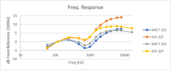
enter image description here

I'm looking for a DIY or professional method for easily measuring frequency response of an audio system from 10Hz to 10kHz. It is for a guitar amplifier, and I would like a better way to characterize my changes without playing actual guitar through it all the time as I'm tweaking.

In the RF world I would use a Vector Analyzer... I was trying to come up with an easy way using a scope and a sweep generator, but have yet to think of a good method. The best I have so far:

  1. Create a DDS system with an Arduino platform and take ADC measurements of the input and output peaks, but that involves a whole project on its own...
  2. Using a DMM on AC mode, but it gets inaccurate above 1kHz it seems. (Faster then reading scope lines)
  3. Some sort of Audacity plugin or program using my PCs audio card? (Nice automated plot or data export?)

I should note my scope does not have auto measure capability, it is from 1978... Otherwise, yes a modern scope I could at least use peak measure as I change the frequency generator.

Currently I occasionally take a pile of hand measurements with a generator and scope. Manually changing the frequency, and writing down the measurements.

enter image description here

I'm looking for a DIY or professional method for easily measuring frequency response of an audio system from 10Hz to 10kHz. It is for a guitar amplifier, and I would like a better way to characterize my changes without playing actual guitar through it all the time as I'm tweaking. Note this is a tube amplifier, so not easy to model.

In the RF world I would use a Vector Analyzer... I was trying to come up with an easy way using a scope and a sweep generator, but have yet to think of a good method. The best I have so far:

  1. Create a DDS system with an Arduino platform and take ADC measurements of the input and output peaks, but that involves a whole project on its own...
  2. Using a DMM on AC mode, but it gets inaccurate above 1kHz it seems. (Faster then reading scope lines)
  3. Some sort of Audacity plugin or program using my PCs audio card? (Nice automated plot or data export?)

I should note my scope does not have auto measure capability, it is from 1978... Otherwise, yes a modern scope I could at least use peak measure as I change the frequency generator.

Currently I occasionally take a pile of hand measurements with a generator and scope. Manually changing the frequency, and writing down the measurements.

enter image description here

Source Link
MadHatter
  • 3.6k
  • 1
  • 21
  • 47

Automated Approaches for Measuring Audio Amplifier Frequency Response

I'm looking for a DIY or professional method for easily measuring frequency response of an audio system from 10Hz to 10kHz. It is for a guitar amplifier, and I would like a better way to characterize my changes without playing actual guitar through it all the time as I'm tweaking.

In the RF world I would use a Vector Analyzer... I was trying to come up with an easy way using a scope and a sweep generator, but have yet to think of a good method. The best I have so far:

  1. Create a DDS system with an Arduino platform and take ADC measurements of the input and output peaks, but that involves a whole project on its own...
  2. Using a DMM on AC mode, but it gets inaccurate above 1kHz it seems. (Faster then reading scope lines)
  3. Some sort of Audacity plugin or program using my PCs audio card? (Nice automated plot or data export?)

I should note my scope does not have auto measure capability, it is from 1978... Otherwise, yes a modern scope I could at least use peak measure as I change the frequency generator.

Currently I occasionally take a pile of hand measurements with a generator and scope. Manually changing the frequency, and writing down the measurements.

enter image description here