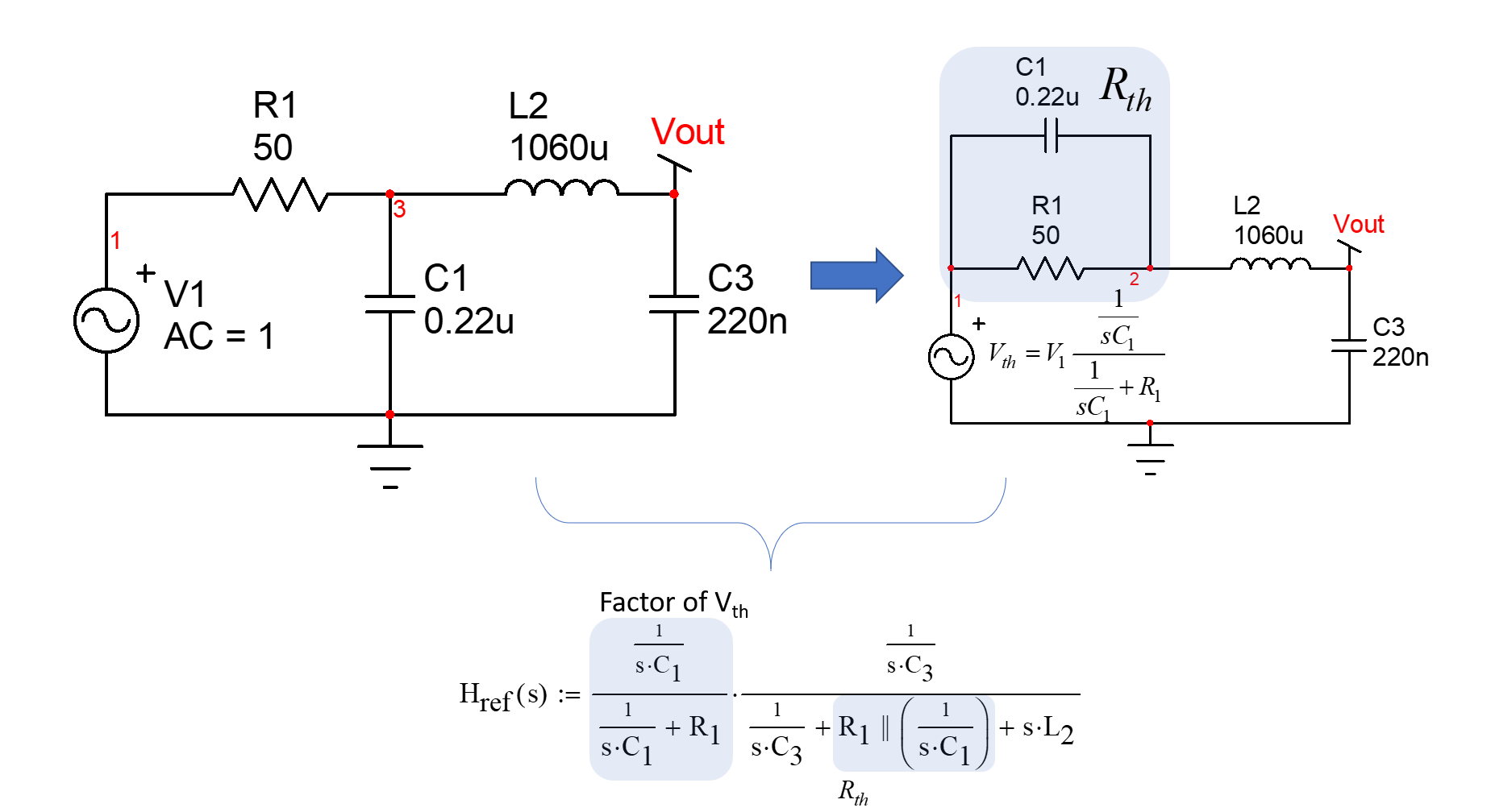
This transfer function can be obtained using brute-force analysis or the fast analytical circuit techniques known as FACTs. For the brute-force approach, you can consider a Thévenin generator featuring the first \$RC\$ filter driving the \$LC\$ network. If you do the maths ok, you should find:
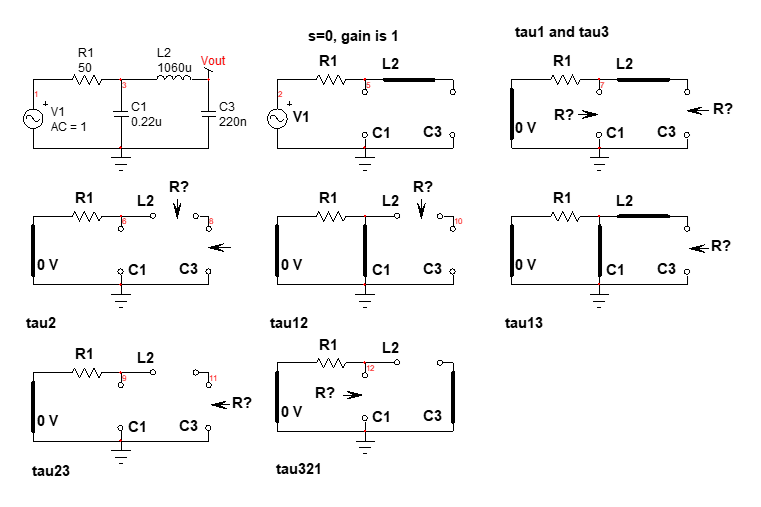
Then you develop all the terms and rearrange to form a 3rd-order polynomial to reveal resonant and cutoff frequencies. The other option is to use the FACTs which will lead you to the coefficients values in one shot, without equations and the risk to make mistakes while developing the above expression. Just go through the time constants determination as shown in the below drawing and you find the transfer function very quickly:
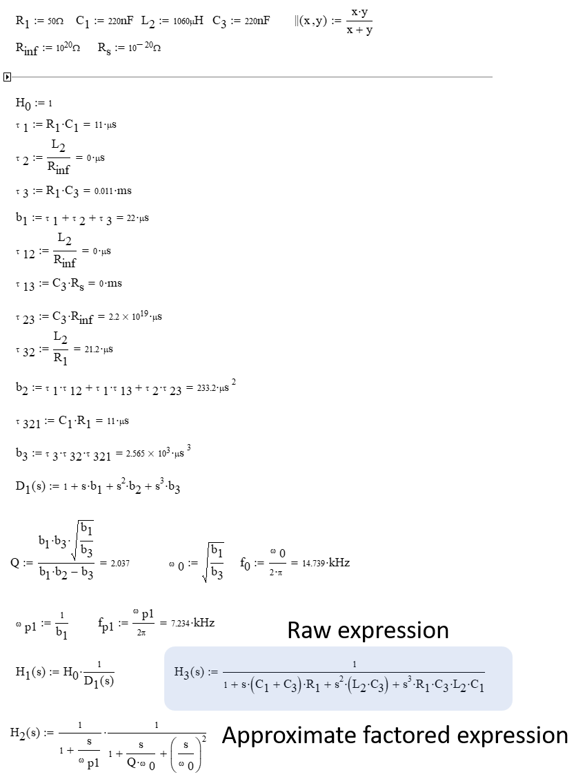
Assemble the time constants in a Mathcad sheet and try to factor the 3rd-oder polynomial with a 1st-order filter dominating the low-frequency response:
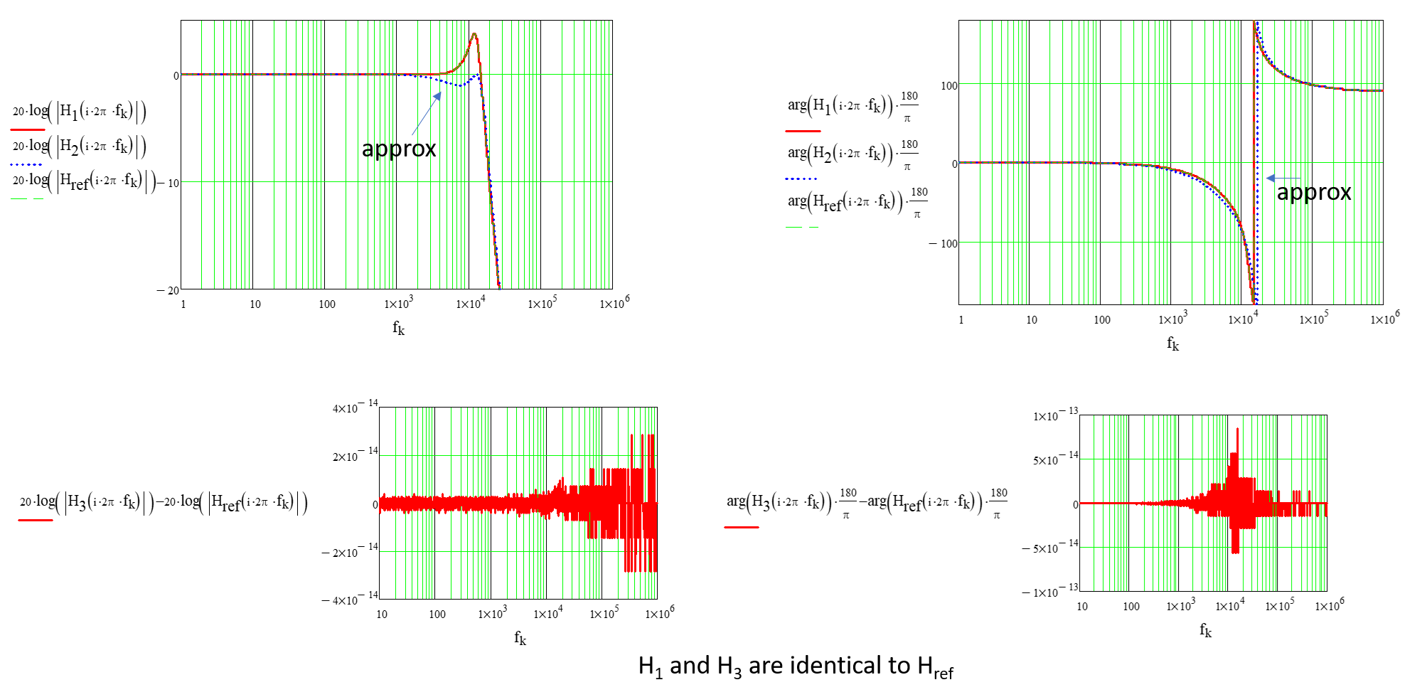
And finally you can plot the ac response. Please note the divergence of the factored expression. This is because the \$RC\$ cutoff frequency is too close to the double poles incurred by the \$LC\$ filter. Increasing \$R_1\$ to 100 \$\Omega\$ gives a better fit:


