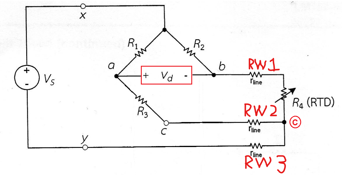
Important Note- the above circuit is only applicable when all the resistances are nominally at the same value i.e. the same magnitude balance current flows into both R1 and R2. I'm mentioning this because if the left half of the bridge has a different impedance to the right half, 3-wire connections to an external device don't produce wire-resistance cancellation correctly. In other words, at balance, R3 must equal R4.
So, I've added a label in red (inside a red circle) called "C". This is the "new lower power feed point" and you can now ignore the old node in black called "C": -
Can you see that R3 is in series with RW2 and equally, R4 is in series with RW1 and hence the balance is maintained.? No? Read below: -
Consider that in balance, R3 equals R4 and R1 equals R2. This produces 0 volts output between "a" and "b". If R3 and R4 both increased by 10%, the bridge would still be in balance. And increasing both by 10% is the same as adding series resistance to them both. That series resistance comes from the interconnecting wires (RW1 and RW2) and, it can be presumed to be identical for both. So the bridge remains in balance no matter what value RW1 and RW2 is providing that they are both the same value.
RW3 is a red-herring because it doesn't imbalance anything when its value changes; it just affects the "gain" of the circuit.

