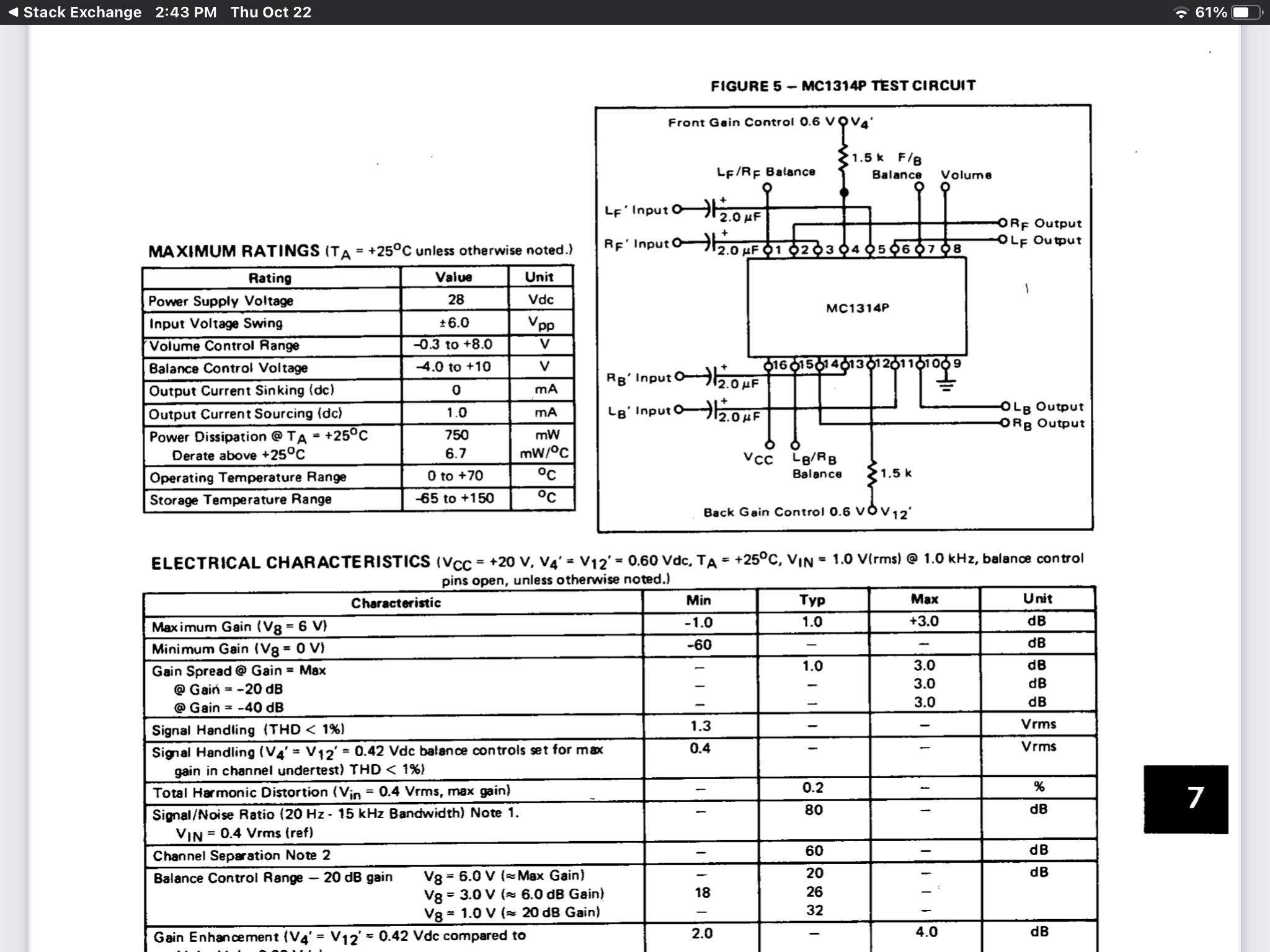
https://datasheetspdf.com/pdf/570328/Motorola/MC1314P/1. For the quad VCA obsolete chip.
Your schematic on the surface looks ok.
Did it overheat immediately? Polarity correct on Vcc, Gnd
https://4donline.ihs.com/images/VipMasterIC/IC/MOTO/MOTOS12755/MOTOS12755-1.pdf?hkey=D9A213CC6FEE7D103EF6B88F2AEB20B8 enter link description here
Beware the pins are shown upside down in the block diagram!
ALSO your cap polarity is backwards
which shorts out the cap!! And may induce excessive DC bias current (?)
why did it blow?
tl;dr = e-caps reversed, causing caps to conduct DC with low ESR, causing differential input Vbe of NPN’s to go negative with 0Vin and +ve emitters, causing Reb=~<10 ohms, causing avalanche punch-thru, causing Vce punchthru and unlimited current across conducting junctions, causing explosive results
with >10W/sqmm causing a crater in the epoxy but perhaps nitnot sustained long enough to blow the e-caps which might have been a bigger explosion with toxic smoke , And;It enough to exceed say a battery thermal runaway which would result in a bigger problem.
most BJT’s have a -5V limit for Vbe.
many e-caps can tolerate -10% of the forward rated voltage for a limited period.
when you aren’t sure try to have current limiting for the size of the junction, BJT or IC or PCB.
use a passive RC filter or PTC oxide resistor for the safe limit might work if it heats up faster and rises in R faster than the junction,
but not in this case.
an active current limiter is pretty easy to setup for experimentation or use an LDO sized appropriately, e.g. LM317

