Try to make things readable.
Source Link
JRE
  • 73.5k
  • 10
  • 112
  • 194

This is what I have done so far   

CALCULATIONS. R_L=8 Ω P_AVG=10W Bandwidth from 20 Hz to 18 kHz V_(0 peak)=√(2×10×8)=12.65v

  • R_L = 8 Ω

  • P_AVG = 10W

  • Bandwidth from 20 Hz to 18 kHz

  • V_(0 peak) = √(2×10×8) = 12.65v

  • V_CC = V_(0 peak)×2+2 = 27.3V ≅ 28V

  • I_(0 peak) = V_(0 peak)/R_L = 12.65/8 = 1.58A

V_CC=V_(0 peak)×2+2=27.3V≅28V I_(0 peak)=V_(0 peak)/R_L =12.65/8=1.58A EachEach transistor current is given by: I_(0 peak)/2=1.58/2=0.79A Assuming β=113 I_(B Q1)=I_(B Q2)=I_E/(β+1)=0.79/114=6.93mA Assuming I_D=1A Then

  • I_(0 peak)/2 = 1.58/2 = 0.79A

Assuming β = 113

  • I_(B Q1) = I_(B Q2) = I_E/(β+1) = 0.79/114 = 6.93mA

Assuming I_D = 1A, then: I_bias=1mA+1mA+6.93mA+6.93mA=15.86mA Setting V_C=14V Then R4=(28V-14v-0.7v-0.7V)/15.86mA=794.5Ω

  • I_bias = 1mA+1mA+6.93mA+6.93mA = 15.86mA

Setting V_E=1V R_3+R_3^II=1V/15.86mA=63.05Ω InputV_C = 14V, then:

  • R4 = (28V-14v-0.7v-0.7V)/15.86mA = 794.5Ω

Setting V_E = 1V

  • R_3+R_3^II = 1V/15.86mA = 63.05Ω

Input current is assumed to be 500mA Q_3 gain is given by V_(O peak rms)/V_(in rms) = √(8×10)/500mA=17.88Ω:

  • V_(O peak rms)/V_(in rms) = √(8×10)/500mA = 17.88Ω

Setting Q_3 gain to 20: R_3^II=((28V-14V)/15.86mA)/20=44.14Ω R_3=63.05-44.14=18.92Ω I_B=I_C/β=15.86mA/100=0.1586mA Setting I_1=20

  • R_3^II = ((28V-14V)/15.86mA)/20=44.14Ω
  • R_3=63.05-44.14 = 18.92Ω
  • I_B = I_C/β = 15.86mA/100 = 0.1586mA

Setting I_1 = 20 I_B I_B=20×0.1586mA=3.172mA R_2=1.7V/3.172mA=535Ω R_1=(28V-1.7V)/3.172mA=8291Ω Designing:

  • I_B = 20×0.1586mA = 3.172mA
  • R_2 = 1.7V/3.172mA = 535Ω
  • R_1 = (28V-1.7V)/3.172mA = 8291Ω

Designing for C_1 and C_3:

r_e=26mV/15.86mA=1. 64Ω R_1 ||R_2=502.57Ω R_3^II=44.14Ω R_th=41.96Ω C1=C3=1/(2×π×f_L×R_th )=1/(2×π×20×44.14)=189.65μF

  • r_e = 26mV/15.86mA = 1.64Ω
  • R_1 ||R_2 = 502.57Ω
  • R_3^II = 44.14Ω
  • R_th = 41.96Ω
  • C1 = C3= 1/(2×π×f_L×R_th) = 1/(2×π×20×44.14) = 189.65μF

Designing for C_2:

R_th=69.6759Ω C_2=10/(2×π×f_L×R_th )=10/(2×π×20×69.6759)=1142μF

  • R_th = 69.6759Ω
  • C_2 = 10/(2×π×f_L×R_th) = 10/(2×π×20×69.6759) = 1142μF

When I simulate the circuit,output the output voltage is quite small and the output power is much less than 10W.What

What could be the issue?   

The final circuit I came up with is shown.

This is what I have done so far  CALCULATIONS. R_L=8 Ω P_AVG=10W Bandwidth from 20 Hz to 18 kHz V_(0 peak)=√(2×10×8)=12.65v

V_CC=V_(0 peak)×2+2=27.3V≅28V I_(0 peak)=V_(0 peak)/R_L =12.65/8=1.58A Each transistor current is given by: I_(0 peak)/2=1.58/2=0.79A Assuming β=113 I_(B Q1)=I_(B Q2)=I_E/(β+1)=0.79/114=6.93mA Assuming I_D=1A Then: I_bias=1mA+1mA+6.93mA+6.93mA=15.86mA Setting V_C=14V Then R4=(28V-14v-0.7v-0.7V)/15.86mA=794.5Ω

Setting V_E=1V R_3+R_3^II=1V/15.86mA=63.05Ω Input current is assumed to be 500mA Q_3 gain is given by V_(O peak rms)/V_(in rms) = √(8×10)/500mA=17.88Ω

Setting Q_3 gain to 20: R_3^II=((28V-14V)/15.86mA)/20=44.14Ω R_3=63.05-44.14=18.92Ω I_B=I_C/β=15.86mA/100=0.1586mA Setting I_1=20 I_B I_B=20×0.1586mA=3.172mA R_2=1.7V/3.172mA=535Ω R_1=(28V-1.7V)/3.172mA=8291Ω Designing for C_1 and C_3

r_e=26mV/15.86mA=1. 64Ω R_1 ||R_2=502.57Ω R_3^II=44.14Ω R_th=41.96Ω C1=C3=1/(2×π×f_L×R_th )=1/(2×π×20×44.14)=189.65μF

Designing for C_2

R_th=69.6759Ω C_2=10/(2×π×f_L×R_th )=10/(2×π×20×69.6759)=1142μF

When I simulate,output voltage is quite small and the output power is much less than 10W.What could be the issue?  The final circuit I came up with is shown.
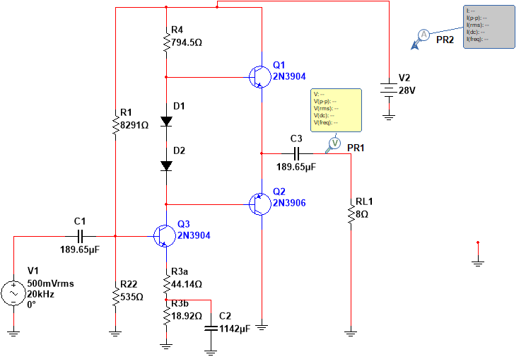
This is what I have done so far 

CALCULATIONS.

  • R_L = 8 Ω

  • P_AVG = 10W

  • Bandwidth from 20 Hz to 18 kHz

  • V_(0 peak) = √(2×10×8) = 12.65v

  • V_CC = V_(0 peak)×2+2 = 27.3V ≅ 28V

  • I_(0 peak) = V_(0 peak)/R_L = 12.65/8 = 1.58A

Each transistor current is given by:

  • I_(0 peak)/2 = 1.58/2 = 0.79A

Assuming β = 113

  • I_(B Q1) = I_(B Q2) = I_E/(β+1) = 0.79/114 = 6.93mA

Assuming I_D = 1A, then:

  • I_bias = 1mA+1mA+6.93mA+6.93mA = 15.86mA

Setting V_C = 14V, then:

  • R4 = (28V-14v-0.7v-0.7V)/15.86mA = 794.5Ω

Setting V_E = 1V

  • R_3+R_3^II = 1V/15.86mA = 63.05Ω

Input current is assumed to be 500mA Q_3 gain is given by:

  • V_(O peak rms)/V_(in rms) = √(8×10)/500mA = 17.88Ω

Setting Q_3 gain to 20:

  • R_3^II = ((28V-14V)/15.86mA)/20=44.14Ω
  • R_3=63.05-44.14 = 18.92Ω
  • I_B = I_C/β = 15.86mA/100 = 0.1586mA

Setting I_1 = 20 I_B:

  • I_B = 20×0.1586mA = 3.172mA
  • R_2 = 1.7V/3.172mA = 535Ω
  • R_1 = (28V-1.7V)/3.172mA = 8291Ω

Designing for C_1 and C_3:

  • r_e = 26mV/15.86mA = 1.64Ω
  • R_1 ||R_2 = 502.57Ω
  • R_3^II = 44.14Ω
  • R_th = 41.96Ω
  • C1 = C3= 1/(2×π×f_L×R_th) = 1/(2×π×20×44.14) = 189.65μF

Designing for C_2:

  • R_th = 69.6759Ω
  • C_2 = 10/(2×π×f_L×R_th) = 10/(2×π×20×69.6759) = 1142μF

When I simulate the circuit, the output voltage is quite small and the output power is much less than 10W.

What could be the issue? 

The final circuit I came up with is shown.
I added what I have currently done
Source Link
Alex Mwaura
  • 31
  • 1
  • 1
  • 7

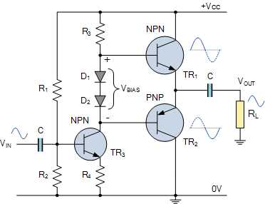
I am required to design a class AB audio amplifier to deliver 10W to an 8Ω speaker as shown, but I don't know where to start. The bandwidth is to cover the range from 20Hz to 18kHz. Input voltage is 500mV rms.

Could anyone guide me please?enter image description here

circuit diagram

Image source: Electronics Tutorials - Class AB Amplifier Driver Stage

I got VoThis is what I have done so far CALCULATIONS. R_L=8 Ω P_AVG=10W Bandwidth from 20 Hz to 18 kHz V_(0 peak as √)=√(10 * 8 * 22×10×8) which gives 12=12.65V65v

V_CC=V_(0 peak)×2+2=27. I then set Vcc=Vo peak*2 +1 which gives 27V3V≅28V I_(0 peak)=V_(0 peak)/R_L =12. How do I get the65/8=1.58A Each transistor current and resistor values?is given by: LoadI_(0 peak)/2=1.58/2=0.79A Assuming β=113 I_(B Q1)=I_(B Q2)=I_E/(β+1)=0.79/114=6.93mA Assuming I_D=1A Then: I_bias=1mA+1mA+6.93mA+6.93mA=15.86mA Setting V_C=14V Then R4=(28V-14v-0.7v-0.7V)/15.86mA=794.5Ω

Setting V_E=1V R_3+R_3^II=1V/15.86mA=63.05Ω Input current Iois assumed to be 500mA Q_3 gain is given by V_(O peak rms)/V_(in rms) = 12 √(8×10)/500mA=17.6588Ω

Setting Q_3 gain to 20: R_3^II=((28V-14V)/15.86mA)/20=44.14Ω R_3=63.05-44.14=18.92Ω I_B=I_C/8 = 1β=15.58A86mA/100=0.1586mA Setting I_1=20 I_B I_B=20×0.1586mA=3.172mA R_2=1.7V/3.172mA=535Ω R_1=(28V-1.7V)/3.172mA=8291Ω Designing for C_1 and C_3

r_e=26mV/15.86mA=1. 64Ω R_1 ||R_2=502.57Ω R_3^II=44.14Ω R_th=41.96Ω C1=C3=1/(2×π×f_L×R_th )=1/(2×π×20×44.14)=189.65μF

Designing for C_2

R_th=69.6759Ω C_2=10/(2×π×f_L×R_th )=10/(2×π×20×69.6759)=1142μF

When I simulate,output voltage is quite small and the output power is much less than 10W.What could be the issue? The final circuit I came up with is shown.

I am required to design a class AB audio amplifier to deliver 10W to an 8Ω speaker as shown, but I don't know where to start. The bandwidth is to cover the range from 20Hz to 18kHz. Input voltage is 500mV rms.

Could anyone guide me please?

circuit diagram

Image source: Electronics Tutorials - Class AB Amplifier Driver Stage

I got Vo peak as √(10 * 8 * 2) which gives 12.65V. I then set Vcc=Vo peak*2 +1 which gives 27V. How do I get the current and resistor values? Load current Io peak = 12.65/8 = 1.58A

I am required to design a class AB audio amplifier to deliver 10W to an 8Ω speaker as shown, but I don't know where to start. The bandwidth is to cover the range from 20Hz to 18kHz. Input voltage is 500mV rms.

enter image description here

circuit diagram

Image source: Electronics Tutorials - Class AB Amplifier Driver Stage

This is what I have done so far CALCULATIONS. R_L=8 Ω P_AVG=10W Bandwidth from 20 Hz to 18 kHz V_(0 peak)=√(2×10×8)=12.65v

V_CC=V_(0 peak)×2+2=27.3V≅28V I_(0 peak)=V_(0 peak)/R_L =12.65/8=1.58A Each transistor current is given by: I_(0 peak)/2=1.58/2=0.79A Assuming β=113 I_(B Q1)=I_(B Q2)=I_E/(β+1)=0.79/114=6.93mA Assuming I_D=1A Then: I_bias=1mA+1mA+6.93mA+6.93mA=15.86mA Setting V_C=14V Then R4=(28V-14v-0.7v-0.7V)/15.86mA=794.5Ω

Setting V_E=1V R_3+R_3^II=1V/15.86mA=63.05Ω Input current is assumed to be 500mA Q_3 gain is given by V_(O peak rms)/V_(in rms) = √(8×10)/500mA=17.88Ω

Setting Q_3 gain to 20: R_3^II=((28V-14V)/15.86mA)/20=44.14Ω R_3=63.05-44.14=18.92Ω I_B=I_C/β=15.86mA/100=0.1586mA Setting I_1=20 I_B I_B=20×0.1586mA=3.172mA R_2=1.7V/3.172mA=535Ω R_1=(28V-1.7V)/3.172mA=8291Ω Designing for C_1 and C_3

r_e=26mV/15.86mA=1. 64Ω R_1 ||R_2=502.57Ω R_3^II=44.14Ω R_th=41.96Ω C1=C3=1/(2×π×f_L×R_th )=1/(2×π×20×44.14)=189.65μF

Designing for C_2

R_th=69.6759Ω C_2=10/(2×π×f_L×R_th )=10/(2×π×20×69.6759)=1142μF

When I simulate,output voltage is quite small and the output power is much less than 10W.What could be the issue? The final circuit I came up with is shown.

Became Hot Network Question
added 40 characters in body
Source Link
Alex Mwaura
  • 31
  • 1
  • 1
  • 7

I am required to design a class AB audio amplifier to deliver 10W to an 8Ω speaker as shown, but I don't know where to start. The bandwidth is to cover the range from 20Hz to 18kHz. Input voltage is 500mV rms.

Could anyone guide me please?

circuit diagram

Image source: Electronics Tutorials - Class AB Amplifier Driver Stage

I got Vo peak as √(10 * 8 * 2) which gives 12.65V. I then set Vcc=Vo peak*2 +1 which gives 27V. How do I get the current and resistor values? Load current Io peak = 12.65/8 = 1.58A

I am required to design a class AB audio amplifier to deliver 10W to an 8Ω speaker as shown, but I don't know where to start. The bandwidth is to cover the range from 20Hz to 18kHz. Input voltage is 500mV rms.

Could anyone guide me please?

circuit diagram

Image source: Electronics Tutorials - Class AB Amplifier Driver Stage

I got Vo peak as √(10 * 8 * 2) which gives 12.65V. I then set Vcc=Vo peak*2 +1 which gives 27V. How do I get the current and resistor values?

I am required to design a class AB audio amplifier to deliver 10W to an 8Ω speaker as shown, but I don't know where to start. The bandwidth is to cover the range from 20Hz to 18kHz. Input voltage is 500mV rms.

Could anyone guide me please?

circuit diagram

Image source: Electronics Tutorials - Class AB Amplifier Driver Stage

I got Vo peak as √(10 * 8 * 2) which gives 12.65V. I then set Vcc=Vo peak*2 +1 which gives 27V. How do I get the current and resistor values? Load current Io peak = 12.65/8 = 1.58A

Added link to image source. Added homework tag. Small grammar / syntax changes, also added spaces so that "*" isn't interpreted as italics (Markdown syntax).
Source Link
SamGibson
  • 18.3k
  • 5
  • 41
  • 63
Loading
added 143 characters in body
Source Link
Alex Mwaura
  • 31
  • 1
  • 1
  • 7
Loading
Correct ohm symbol, and other minor clean-up.
Source Link
Loading
added 18 characters in body
Source Link
Alex Mwaura
  • 31
  • 1
  • 1
  • 7
Loading
Source Link
Alex Mwaura
  • 31
  • 1
  • 1
  • 7
Loading