Notice removed Canonical answer required by CommunityBot
Bounty Ended with no winning answer by CommunityBot
Tweeted twitter.com/StackElectronix/status/1336777691056451586
Added small signal model
Source Link
RAN
  • 329
  • 4
  • 18

So I am designing an OTA, exactly like Miller OTA, but I tried to see the behaviour without Miller compensation. The circuit diagram is shown below enter image description here
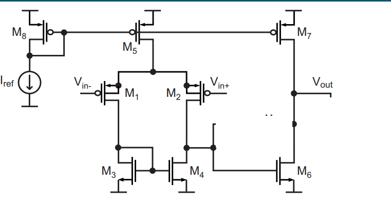
As seen there is no compensation network, neither is the output loaded. If connected in unty gain configuration i.e Vout shorted to Vin- then I get a frequency response with gain peaking as shown below enter image description here
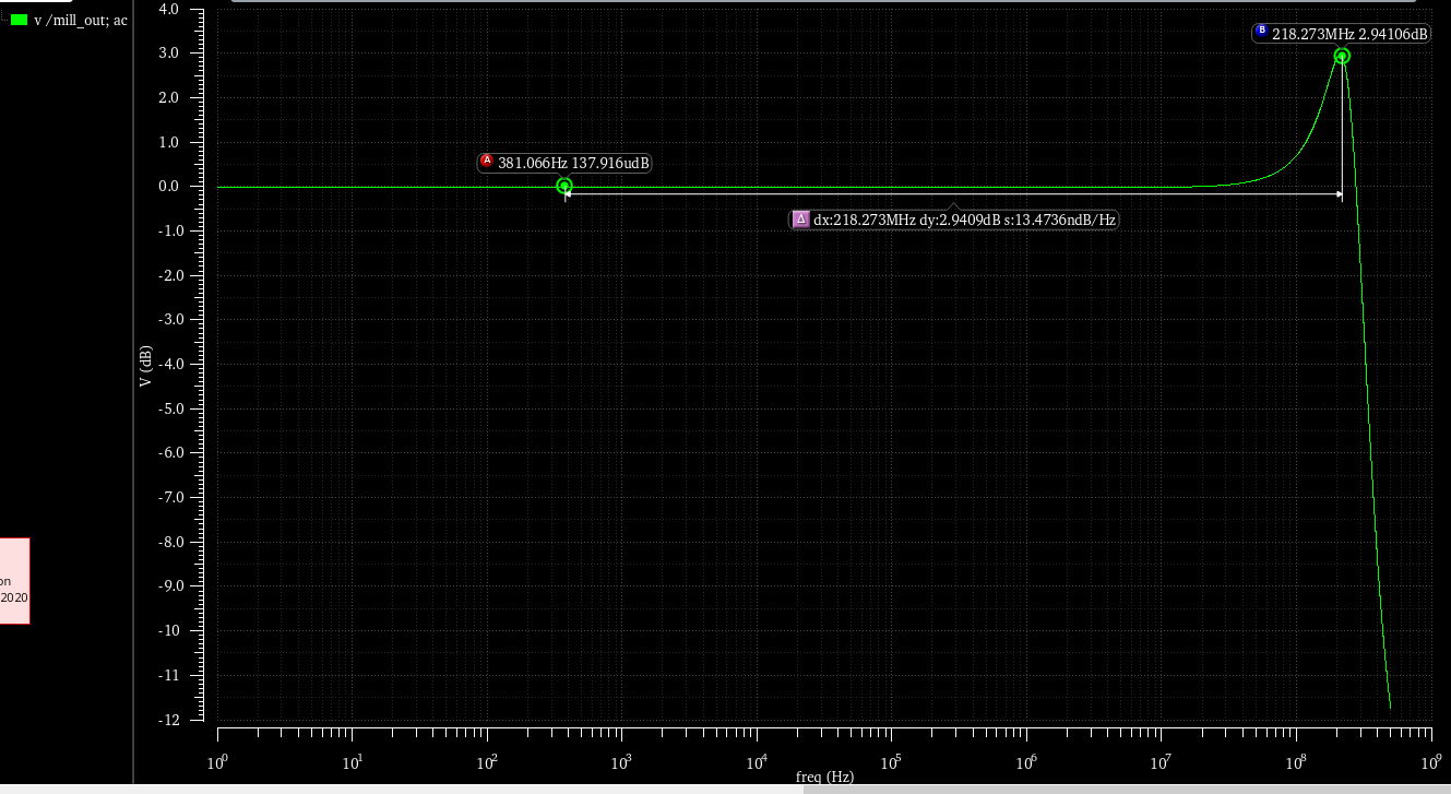
This suggest that there is complex conjugate pole. So I went ahead with the small signal analysis. The input signal is connected in Vin+ hence $$ \frac{Vo}{Vin} = \frac{1}{1+\frac{1+sr1C1}{gm2\cdot gm6\cdot r1\cdot r2 - (sCin \cdot r2)(1+sr1C1)}}$$ where \$ r1=ro2 \parallel ro4 \$ ;\$ r2=ro7 \parallel ro6 \$ \$ Cin \$ is capacitance between gate and source of M1 and C1 is capacitance between gate and source of M6. This equation checks out because for DC, the gain is \$ \frac{Vo}{Vin} = \frac{1}{1+\frac{1}{gm2\cdot gm6\cdot r1\cdot r2}} \$ and assuming \$ gm2\cdot gm6\cdot r1\cdot r2 >> 1\$ the gain is roughly equal to one. Now to find the complex poles I would like to get the equation in the standard format which is

enter image description here

And this is where I am stuck. So my questions are as follows:

  1. Is the gain equation correct?
  2. Can anyone show me how to get this in standard form? I am guessing there will be a zero as well with a value r1C1.

EDIT: I end up with the following equation which does not make sense to me: $$ \frac{Vo}{Vin} = \frac{gm2\cdot gm1\cdot r2\cdot r1 -s\cdot Cin\cdot r2 + s^2 \cdot r1\cdot r2\cdot C1\cdot Cin}{s^2 \cdot r1\cdot r2\cdot C1\cdot Cin +s\cdot (r1c1-r2cin) +gm2\cdot gm1\cdot r2\cdot r1 +1}$$

EDIT: Added small signal model for reference enter image description here

So I am designing an OTA, exactly like Miller OTA, but I tried to see the behaviour without Miller compensation. The circuit diagram is shown below enter image description here

As seen there is no compensation network, neither is the output loaded. If connected in unty gain configuration i.e Vout shorted to Vin- then I get a frequency response with gain peaking as shown below enter image description here

This suggest that there is complex conjugate pole. So I went ahead with the small signal analysis. The input signal is connected in Vin+ hence $$ \frac{Vo}{Vin} = \frac{1}{1+\frac{1+sr1C1}{gm2\cdot gm6\cdot r1\cdot r2 - (sCin \cdot r2)(1+sr1C1)}}$$ where \$ r1=ro2 \parallel ro4 \$ ;\$ r2=ro7 \parallel ro6 \$ \$ Cin \$ is capacitance between gate and source of M1 and C1 is capacitance between gate and source of M6. This equation checks out because for DC, the gain is \$ \frac{Vo}{Vin} = \frac{1}{1+\frac{1}{gm2\cdot gm6\cdot r1\cdot r2}} \$ and assuming \$ gm2\cdot gm6\cdot r1\cdot r2 >> 1\$ the gain is roughly equal to one. Now to find the complex poles I would like to get the equation in the standard format which is

enter image description here

And this is where I am stuck. So my questions are as follows:

  1. Is the gain equation correct?
  2. Can anyone show me how to get this in standard form? I am guessing there will be a zero as well with a value r1C1.

EDIT: I end up with the following equation which does not make sense to me: $$ \frac{Vo}{Vin} = \frac{gm2\cdot gm1\cdot r2\cdot r1 -s\cdot Cin\cdot r2 + s^2 \cdot r1\cdot r2\cdot C1\cdot Cin}{s^2 \cdot r1\cdot r2\cdot C1\cdot Cin +s\cdot (r1c1-r2cin) +gm2\cdot gm1\cdot r2\cdot r1 +1}$$

EDIT: Added small signal model for reference enter image description here

deleted 28 characters in body
Source Link
Voltage Spike
  • 88.8k
  • 49
  • 90
  • 234

So I am designing an OTA, exactly like Miller OTA, but I tried to see the behaviour without Miller compensation. The circuit diagram is shown below enter image description here

As seen there is no compensation network, neither is the output loaded. If connected in unty gain configuration i.e Vout shorted to Vin- then I get a frequency response with gain peaking as shown below enter image description here

This suggest that there is complex conjugate pole. So I went ahead with the small signal analysis. The input signal is connected in Vin+ hence $$ \frac{Vo}{Vin} = \frac{1}{1+\frac{1+sr1C1}{gm2\cdot gm6\cdot r1\cdot r2 - (sCin \cdot r2)(1+sr1C1)}}$$ where \$ r1=ro2 \parallel ro4 \$ ;\$ r2=ro7 \parallel ro6 \$ \$ Cin \$ is capacitance between gate and source of M1 and C1 is capacitance between gate and source of M6. This equation checks out because for DC, the gain is \$ \frac{Vo}{Vin} = \frac{1}{1+\frac{1}{gm2\cdot gm6\cdot r1\cdot r2}} \$ and assuming \$ gm2\cdot gm6\cdot r1\cdot r2 >> 1\$ the gain is roughly equal to one. Now to find the complex poles I would like to get the equation in the standard format which is

enter image description here

And this is where I am stuck. So my questions are as follows:

  1. Is the gain equation correct?
  2. Can anyone show me how to get this in standard form? I am guessing there will be a zero as well with a value r1C1.

Any help will be appreciated

EDIT: I end up with the following equation which does not make sense to me: $$ \frac{Vo}{Vin} = \frac{gm2\cdot gm1\cdot r2\cdot r1 -s\cdot Cin\cdot r2 + s^2 \cdot r1\cdot r2\cdot C1\cdot Cin}{s^2 \cdot r1\cdot r2\cdot C1\cdot Cin +s\cdot (r1c1-r2cin) +gm2\cdot gm1\cdot r2\cdot r1 +1}$$

So I am designing an OTA, exactly like Miller OTA, but I tried to see the behaviour without Miller compensation. The circuit diagram is shown below enter image description here

As seen there is no compensation network, neither is the output loaded. If connected in unty gain configuration i.e Vout shorted to Vin- then I get a frequency response with gain peaking as shown below enter image description here

This suggest that there is complex conjugate pole. So I went ahead with the small signal analysis. The input signal is connected in Vin+ hence $$ \frac{Vo}{Vin} = \frac{1}{1+\frac{1+sr1C1}{gm2\cdot gm6\cdot r1\cdot r2 - (sCin \cdot r2)(1+sr1C1)}}$$ where \$ r1=ro2 \parallel ro4 \$ ;\$ r2=ro7 \parallel ro6 \$ \$ Cin \$ is capacitance between gate and source of M1 and C1 is capacitance between gate and source of M6. This equation checks out because for DC, the gain is \$ \frac{Vo}{Vin} = \frac{1}{1+\frac{1}{gm2\cdot gm6\cdot r1\cdot r2}} \$ and assuming \$ gm2\cdot gm6\cdot r1\cdot r2 >> 1\$ the gain is roughly equal to one. Now to find the complex poles I would like to get the equation in the standard format which is

enter image description here

And this is where I am stuck. So my questions are as follows:

  1. Is the gain equation correct?
  2. Can anyone show me how to get this in standard form? I am guessing there will be a zero as well with a value r1C1.

EDIT: I end up with the following equation which does not make sense to me: $$ \frac{Vo}{Vin} = \frac{gm2\cdot gm1\cdot r2\cdot r1 -s\cdot Cin\cdot r2 + s^2 \cdot r1\cdot r2\cdot C1\cdot Cin}{s^2 \cdot r1\cdot r2\cdot C1\cdot Cin +s\cdot (r1c1-r2cin) +gm2\cdot gm1\cdot r2\cdot r1 +1}$$

Notice added Canonical answer required by RAN
Bounty Started worth 50 reputation by RAN
simplified the equation for gain
Source Link
RAN
  • 329
  • 4
  • 18

So I am designing an OTA, exactly like Miller OTA, but I tried to see the behaviour without Miller compensation. The circuit diagram is shown below enter image description here

As seen there is no compensation network, neither is the output loaded. If connected in unty gain configuration i.e Vout shorted to Vin- then I get a frequency response with gain peaking as shown below enter image description here

This suggest that there is complex conjugate pole. So I went ahead with the small signal analysis. The input signal is connected in Vin+ hence $$ \frac{Vo}{Vin} = \frac{1}{1+\frac{1+sr1C1}{gm2\cdot gm6\cdot r1\cdot r2 - (sCin \cdot r2)(1+sr1C1)}}$$ where \$ r1=ro2 \parallel ro4 \$ ;\$ r2=ro7 \parallel ro6 \$ \$ Cin \$ is capacitance between gate and source of M1 and C1 is capacitance between gate and source of M6. This equation checks out because for DC, the gain is \$ \frac{Vo}{Vin} = \frac{1}{1+\frac{1}{gm2\cdot gm6\cdot r1\cdot r2}} \$ and assuming \$ gm2\cdot gm6\cdot r1\cdot r2 >> 1\$ the gain is roughly equal to one. Now to find the complex poles I would like to get the equation in the standard format which is

enter image description here

And this is where I am stuck. So my questions are as follows:

  1. Is the gain equation correct?
  2. Can anyone show me how to get this in standard form? I am guessing there will be a zero as well with a value r1C1.

Any help will be appreciated

EDIT: I end up with the following equation which does not make sense to me: $$ \frac{Vo}{Vin} = \frac{gm2\cdot gm1\cdot r2\cdot r1 -s\cdot Cin\cdot r2 + s^2 \cdot r1\cdot r2\cdot C1\cdot Cin}{s^2 \cdot r1\cdot r2\cdot C1\cdot Cin +s\cdot (r1c1-r2cin) +gm2\cdot gm1\cdot r2\cdot r1 +1}$$

So I am designing an OTA, exactly like Miller OTA, but I tried to see the behaviour without Miller compensation. The circuit diagram is shown below enter image description here

As seen there is no compensation network, neither is the output loaded. If connected in unty gain configuration i.e Vout shorted to Vin- then I get a frequency response with gain peaking as shown below enter image description here

This suggest that there is complex conjugate pole. So I went ahead with the small signal analysis. The input signal is connected in Vin+ hence $$ \frac{Vo}{Vin} = \frac{1}{1+\frac{1+sr1C1}{gm2\cdot gm6\cdot r1\cdot r2 - (sCin \cdot r2)(1+sr1C1)}}$$ where \$ r1=ro2 \parallel ro4 \$ ;\$ r2=ro7 \parallel ro6 \$ \$ Cin \$ is capacitance between gate and source of M1 and C1 is capacitance between gate and source of M6. This equation checks out because for DC, the gain is \$ \frac{Vo}{Vin} = \frac{1}{1+\frac{1}{gm2\cdot gm6\cdot r1\cdot r2}} \$ and assuming \$ gm2\cdot gm6\cdot r1\cdot r2 >> 1\$ the gain is roughly equal to one. Now to find the complex poles I would like to get the equation in the standard format which is

enter image description here

And this is where I am stuck. So my questions are as follows:

  1. Is the gain equation correct?
  2. Can anyone show me how to get this in standard form? I am guessing there will be a zero as well with a value r1C1.

Any help will be appreciated

EDIT: I end up with the following equation which does not make sense to me: $$ \frac{Vo}{Vin} = \frac{gm2\cdot gm1\cdot r2\cdot r1 -s\cdot Cin\cdot r2 + s^2 \cdot r1\cdot r2\cdot C1\cdot Cin}{s^2 \cdot r1\cdot r2\cdot C1\cdot Cin +s\cdot (r1c1-r2cin) +gm2\cdot gm1\cdot r2\cdot r1 +1}$$

Source Link
RAN
  • 329
  • 4
  • 18
Loading