edited body
Source Link
Marko Buršič
  • 24.5k
  • 2
  • 21
  • 34

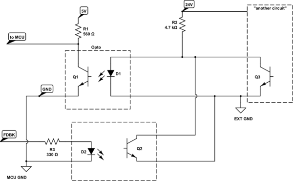
Almost the same, but improved since it has a galvanic isolation and inverted output. However your exaple implies that "another circuit" is sink output (open collector).

  • When the Q3 isn't conducting the LED of 1st opto glows and you get a low signal state on MCU input.
  • When Q3 conducts, the 1st opto LED doesn't glow, so you get a high signal state on MCU input
  • If the signal FDBCK from MCU is high, the 2nd opto LED glows and whatever state of Q3 is, the Vce voltage is low, so this feedback can be detected if Q3 is not conducting.
schematic

simulate this circuit – Schematic created using CircuitLab

Almost the same, but improved since it has a galvanic isolation and inverted output. However your exaple implies that "another circuit" is sink output (open collector).

schematic

simulate this circuit – Schematic created using CircuitLab
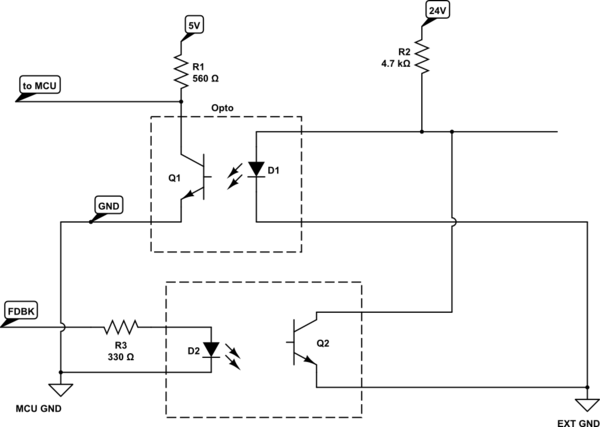
Almost the same, but improved since it has a galvanic isolation and inverted output. However your exaple implies that "another circuit" is sink output (open collector).

  • When the Q3 isn't conducting the LED of 1st opto glows and you get a low signal state on MCU input.
  • When Q3 conducts, the 1st opto LED doesn't glow, so you get a high signal state on MCU input
  • If the signal FDBCK from MCU is high, the 2nd opto LED glows and whatever state of Q3 is, the Vce voltage is low, so this feedback can be detected if Q3 is not conducting.

schematic

simulate this circuit – Schematic created using CircuitLab
edited body
Source Link
Marko Buršič
  • 24.5k
  • 2
  • 21
  • 34

Almost the same, but improved since it has a galvanic isolation and inverted output. However your exaple implies that "another circuit" is sink output (open collector).

schematicschematic

simulate this circuitsimulate this circuit – Schematic created using CircuitLab

Almost the same, but improved since it has a galvanic isolation and inverted output. However your exaple implies that "another circuit" is sink output (open collector).

schematic

simulate this circuit – Schematic created using CircuitLab

Almost the same, but improved since it has a galvanic isolation and inverted output. However your exaple implies that "another circuit" is sink output (open collector).

schematic

simulate this circuit – Schematic created using CircuitLab

edited body
Source Link
Marko Buršič
  • 24.5k
  • 2
  • 21
  • 34

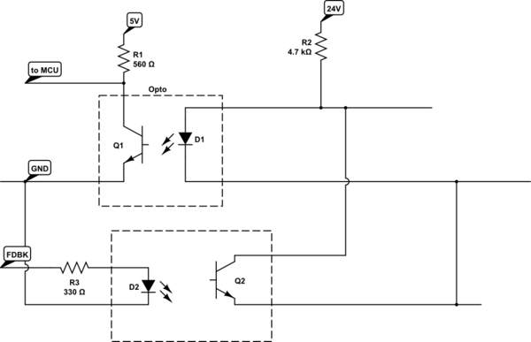
Almost the same, but improved since it has a galvanic isolation and inverted output. However your exaple implies that "another circuit" is sink output (open collector).

schematicschematic

simulate this circuitsimulate this circuit – Schematic created using CircuitLab

Almost the same, but improved since it has a galvanic isolation

schematic

simulate this circuit – Schematic created using CircuitLab

Almost the same, but improved since it has a galvanic isolation and inverted output. However your exaple implies that "another circuit" is sink output (open collector).

schematic

simulate this circuit – Schematic created using CircuitLab

Source Link
Marko Buršič
  • 24.5k
  • 2
  • 21
  • 34
Loading