Microcontrollers make doing these stuff really easy to be honest!
Take this as an example:
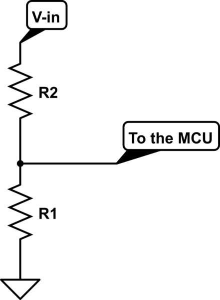
The input is connected to your microcontroller like this:

simulate this circuit – Schematic created using CircuitLab
This is a voltage divider, and the ratio works like this(to a good approximation):
Vout/Vin = R1/(R1+R2)
2 things to note here:
- This is rather a very simple way and not very efficient for that matter, but larger resistors (to an extent) would do the trick.
- MCU should not be connected to live lines, it's a good practice not to at least! so if that input voltage is not isolated, you do need to take care of that.
A much better way, for instance, would be to trigger the microcontroller through a transformer when the transition from 0V to the peak voltage happens (look at impulse response), then you have isolated your input and saved power, but you cannot leave the input on for too long, other wise it might damage the transformer (might wanna use a cap in series with your transformer)! lot of other ways out there(optocouplers in general), but I'd rather stick to the basics.
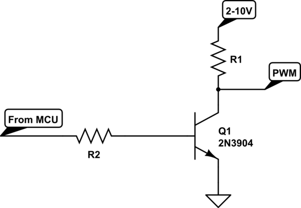
Then, you can use a transistor to make your PWM signal:

Important thing to note here: The type of the transistor you use would depend on your load, the amount of current and these stuff. but if you are trying to drive a motor or sth similar, there are chips with built-in comparators for generating PWMs and a push-pull output.
P.S: I don't know how you are thinking of getting the 2-10V peak (batteries?) for your output, but if one power source is to be used, you ought to think about converting that 20-30V into the 2-10V range. look into DC-DC converters for that matter.
