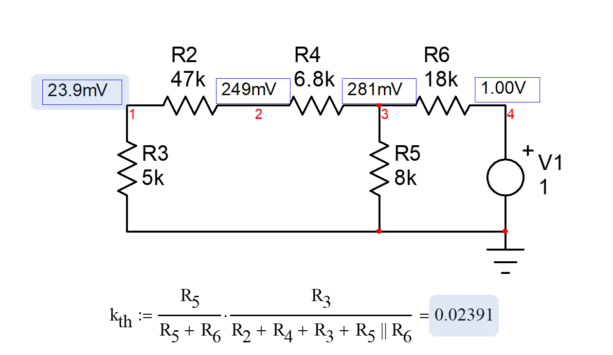
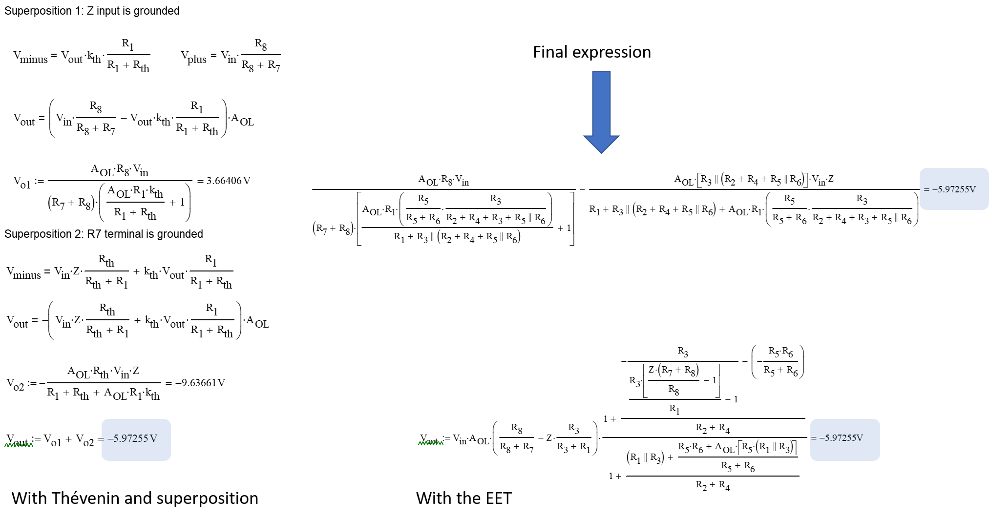
The possible option I see for this circuit is to use the extra-element theorem or EET forged by Dr. Middlebrook some decades ago. You first identify an element that complicates the analysis. Here, it would be the series connection of \$R_3\$ and \$R_4\$. You have the choice to either bring it to infinity (temporarily remove the resistors from the circuit) or short it (replace the resistors by a wire). I have chosen to bring the element to infinity as it makes the circuit simpler to solve. This result would be the reference voltage I need to determine with the help of the below sketch:
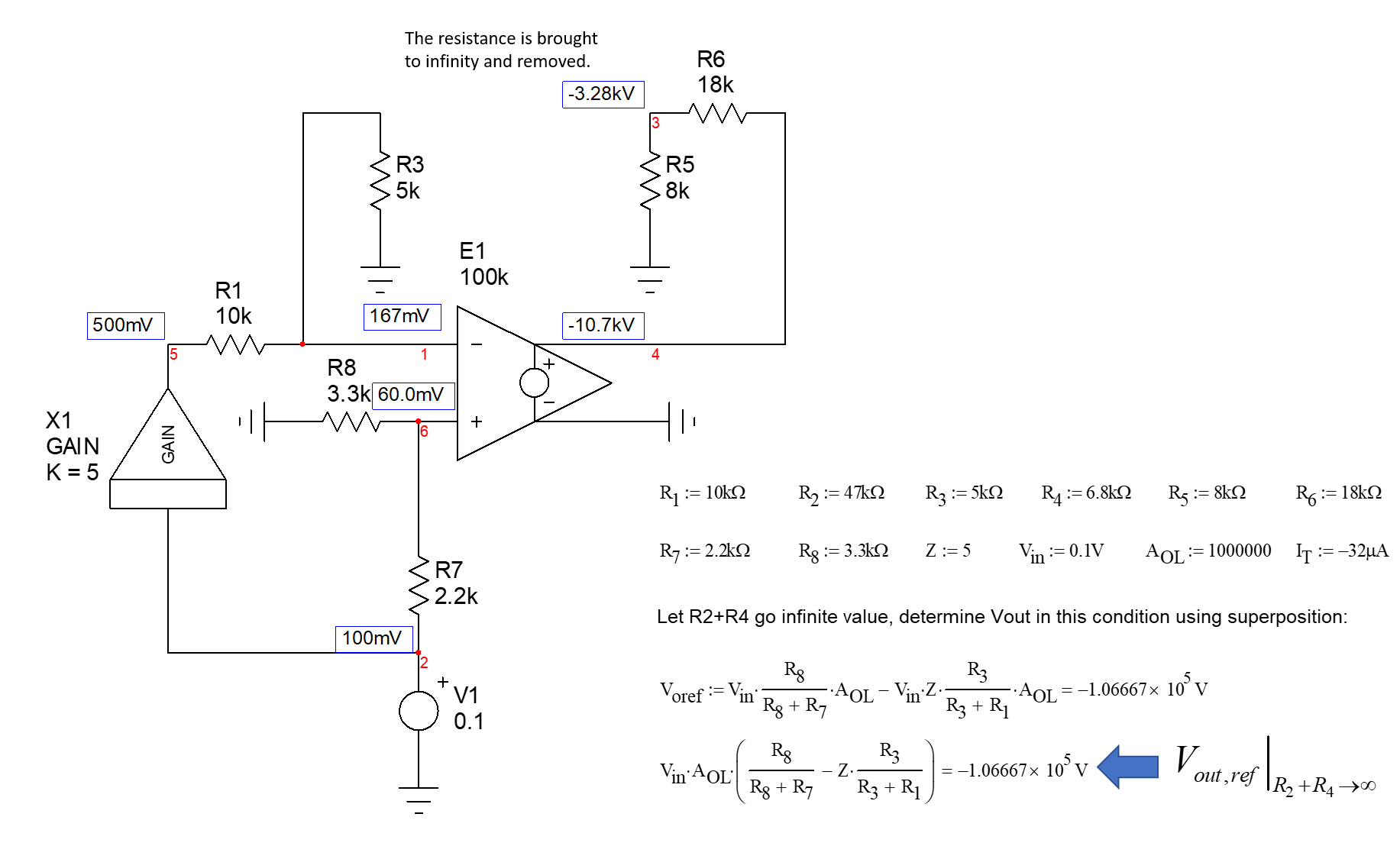
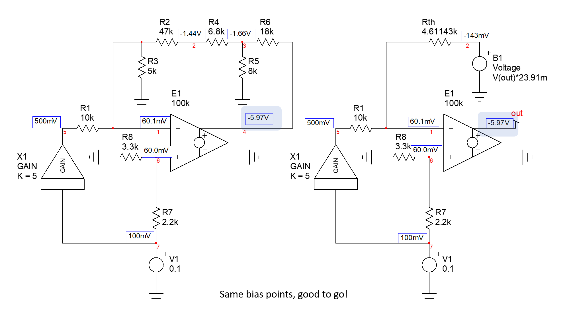
Here, I applied superposition to determine the output voltage at node 4. I can use SPICE with a bias point calculation to check if my result is correct with the arbitrarily-assigned values to the resistances and input source. The open-loop gain of the op-amp is purposely made finite as in your circuit and will disappear later on.
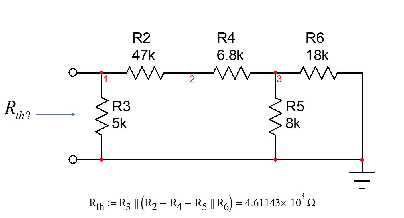
With the value on hand, I can now carry on and determine the resistance "seen" from the connecting terminals of \$R_3\$ and \$R_4\$ when the input source is zeroed. I have built another sketch and will simulate it to make sure my calculations are correct:
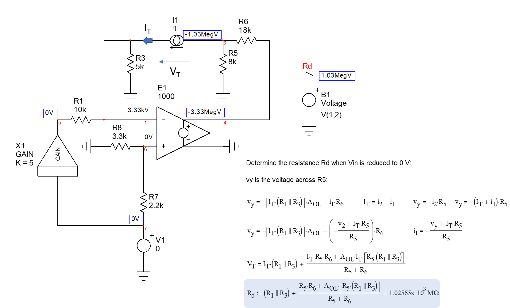
You need a few lines of algebra but nothing complicated to determine this resistance. Again, the cool thing is that you immediately check if the result matches the simulation. This is the case.
Finally, you determine the resistance "seen" from the connecting terminals of \$R_3\$ and \$R_4\$ when the output you want is nulled. A null means the output is 0 V but current can go through it, a bit like the virtual ground of an op-amp. The new circuit is shown below:
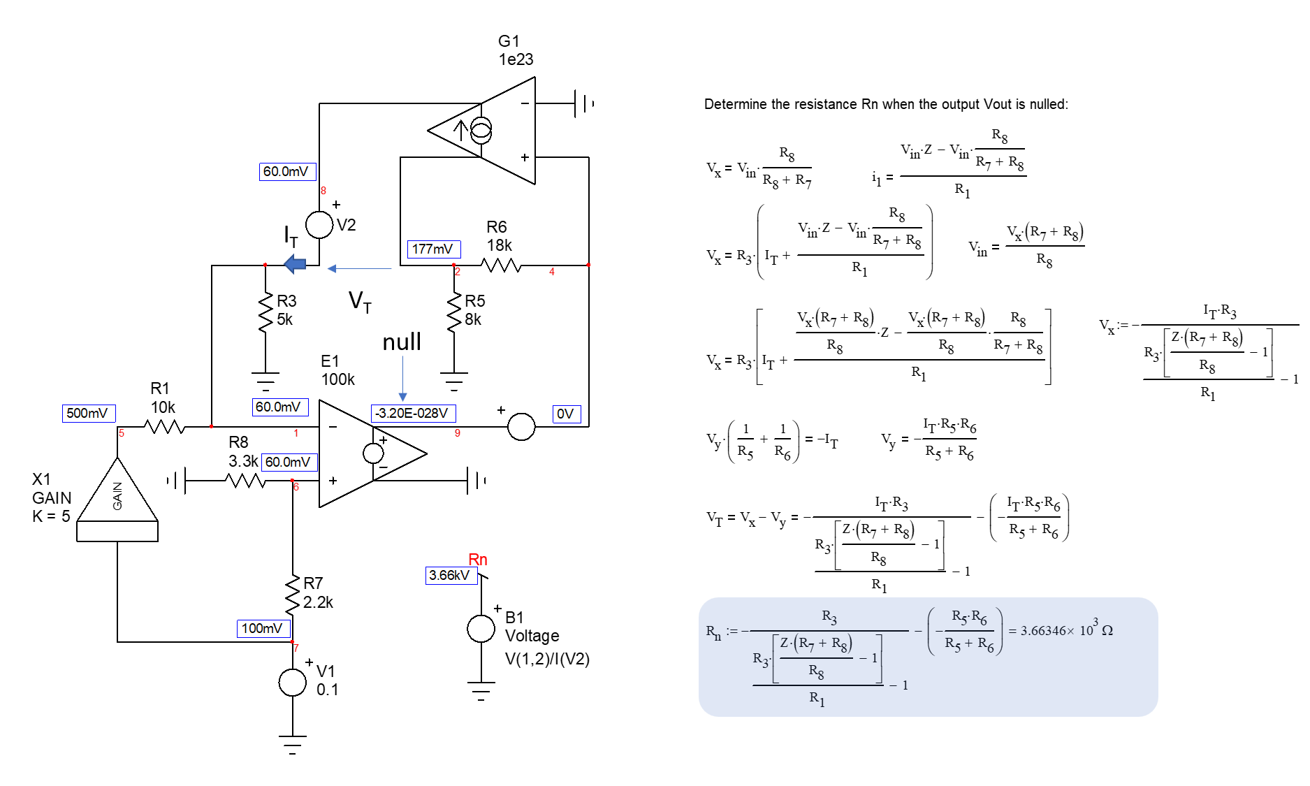
The circuit uses an extra source \$G_1\$ to force the test current \$I_T\$ in the circuit to null the output. It is described in the book I wrote on the fast analytical circuits techniques (FACTs) which also introduces the EET. This is is my modest contribution to the analysis which lets you simulate the resistance driving the element while provoking an output null. As you can see, calculated and simulated values perfectly match.
Now that we have all elements in hands, we can assemble the pieces according to the EET:
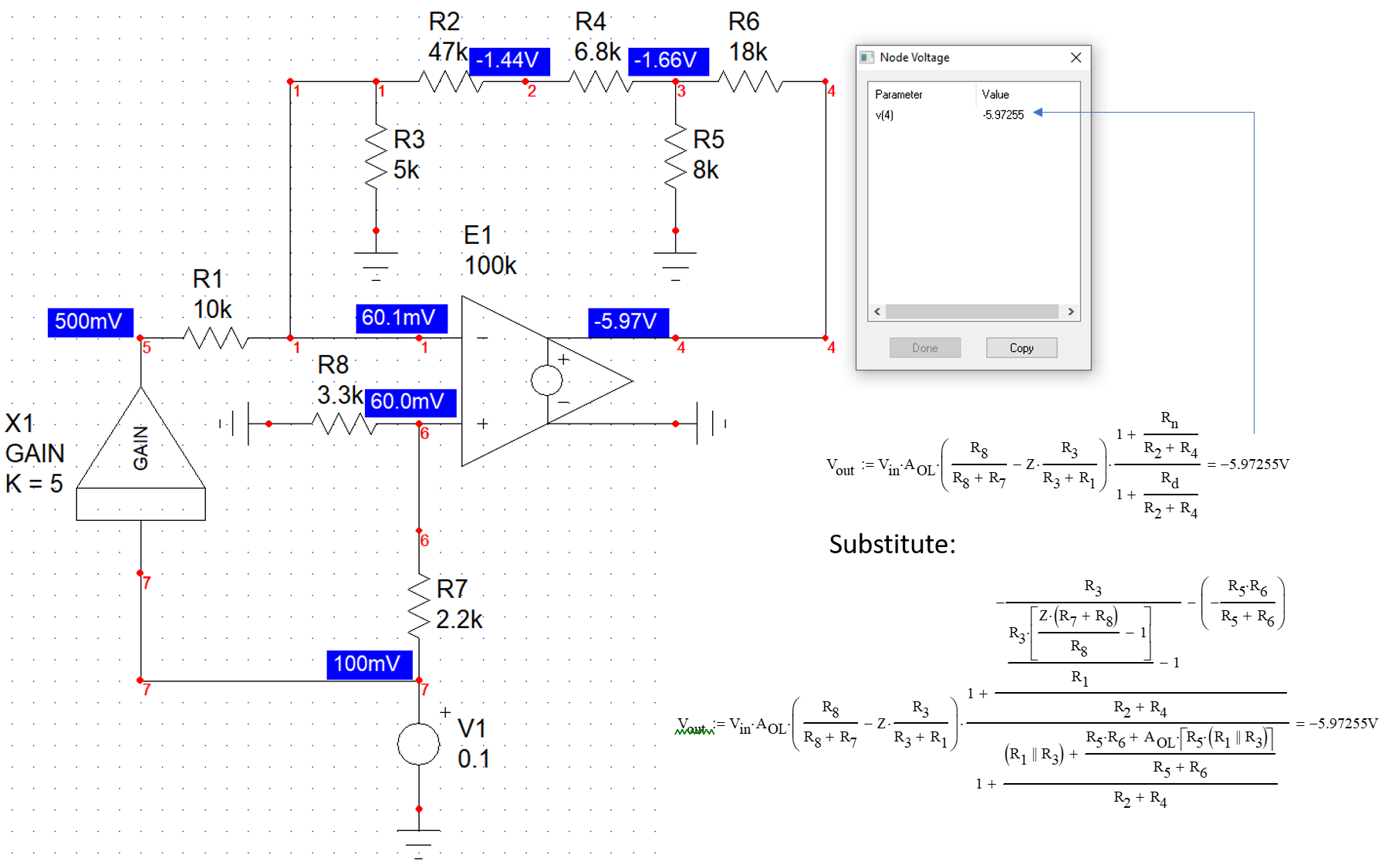
You can also factor the finite open-loop gain of the op-amp and obtain a simplified expression - still ugly :-) expressing the output voltage with an arbitrary input bias of 100 mV:

As you can see, the EET lets you split your complicated circuit into smaller sketches that you can individually solve and, more importantly, simulate to verify them. This is what I do all the times and it saved me in many occasion. This is the divide-and-conquer strategy promoted with the FACTs. You can acquire the skill with simpler passive circuits first and then complicate the analysis petit à petit (step by step).
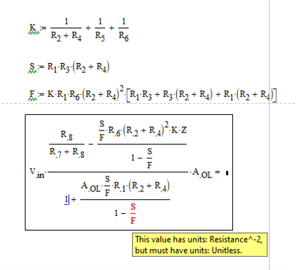
By the way, I have tried your formula but there seems to be an homogeneity problem detected by Mathcad, unless I made a mistake while capturing it (let me know otherwise):
