Added power-on-reset circuit to "set" input of D-type flip flop
Source Link
user173271
user173271

Terminating a monostable pulseTerminating a monostable's output pulse

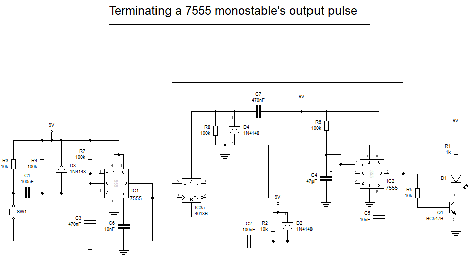
IC1 and its associated components are just a switch debouncer. C2 & R2 trigger IC2 on the falling (trailing) edge of the pulse coming from IC1. IC3a (a positive edge triggered D-Type flip flop) holds IC2 either in reset or enable dependent upon the circuit's output state at the time of the rising (leading) edge of the pulse coming from IC1. A transistor is used to drive the LED to ensure that IC3a's D input sees a sufficiently high logic 1 level voltage. If the circuit triggers at powerup andIn this is a problem then addedit I have added a power-on-reset circuit to the asynchronous set pin (S) of IC3a.

I have built and tested the circuit, it works well.

Terminating a monostable pulse

IC1 and its associated components are just a switch debouncer. C2 & R2 trigger IC2 on the falling (trailing) edge of the pulse coming from IC1. IC3a (a positive edge triggered D-Type flip flop) holds IC2 either in reset or enable dependent upon the circuit's output state at the time of the rising (leading) edge of the pulse coming from IC1. A transistor is used to drive the LED to ensure that IC3a's D input sees a sufficiently high logic 1 level voltage. If the circuit triggers at powerup and this is a problem then add a power-on-reset circuit to the asynchronous set pin (S) of IC3a.

Terminating a monostable's output pulse

IC1 and its associated components are just a switch debouncer. C2 & R2 trigger IC2 on the falling (trailing) edge of the pulse coming from IC1. IC3a (a positive edge triggered D-Type flip flop) holds IC2 either in reset or enable dependent upon the circuit's output state at the time of the rising (leading) edge of the pulse coming from IC1. A transistor is used to drive the LED to ensure that IC3a's D input sees a sufficiently high logic 1 level voltage. In this edit I have added a power-on-reset circuit to the asynchronous set pin (S) of IC3a.

I have built and tested the circuit, it works well.

Increase size of C3 to reduce chances of multiple triggering due to switch bouncing.
Source Link
user173271
user173271

Terminated monostableTerminating a monostable pulse

IC1 and its associated components are just a switch debouncer. C2 & R2 trigger IC2 on the falling (trailing) edge of the pulse coming from IC1. IC3a (a positive edge triggered D-Type flip flop) holds IC2 either in reset or enable dependent upon the circuit's output state at the time of the rising (leading) edge of the pulse coming from IC1. A transistor is used to drive the LED to ensure that IC3a's D input sees a sufficiently high logic 1 level voltage. If the circuit triggers at powerup and this is a problem then add a power-on-reset circuit to the asynchronous set pin (S) of IC3a.

Terminated monostable

IC1 and its associated components are just a switch debouncer. C2 & R2 trigger IC2 on the falling (trailing) edge of the pulse coming from IC1. IC3a (a positive edge triggered D-Type flip flop) holds IC2 either in reset or enable dependent upon the circuit's output state at the time of the rising edge of the pulse coming from IC1. A transistor is used to drive the LED to ensure that IC3a's D input sees a sufficiently high logic 1 level voltage. If the circuit triggers at powerup and this is a problem then add a power-on-reset circuit to the asynchronous set pin (S) of IC3a.

Terminating a monostable pulse

IC1 and its associated components are just a switch debouncer. C2 & R2 trigger IC2 on the falling (trailing) edge of the pulse coming from IC1. IC3a (a positive edge triggered D-Type flip flop) holds IC2 either in reset or enable dependent upon the circuit's output state at the time of the rising (leading) edge of the pulse coming from IC1. A transistor is used to drive the LED to ensure that IC3a's D input sees a sufficiently high logic 1 level voltage. If the circuit triggers at powerup and this is a problem then add a power-on-reset circuit to the asynchronous set pin (S) of IC3a.

Changing Power-On-Reset instructions.
Source Link
user173271
user173271

Terminated monostable

IC1 and its associated components are just a switch debouncer. C2 & R2 trigger IC2 on the falling (trailing) edge of the pulse coming from IC1. IC3a (a positive edge triggered D-Type flip flop) holds IC2 either in reset or enable dependent upon the circuit's output state at the time of the rising edge of the pulse coming from IC1. A transistor is used to drive the LED to ensure that IC3a's D input sees a sufficiently high logic 1 level voltage. If the circuit triggers at powerup and this is a problem then add a power-on-reset circuit to the resetasynchronous set pin (S) of IC1IC3a.

Terminated monostable

IC1 and its associated components are just a switch debouncer. C2 & R2 trigger IC2 on the falling (trailing) edge of the pulse coming from IC1. IC3a (a positive edge triggered D-Type flip flop) holds IC2 either in reset or enable dependent upon the circuit's output state at the time of the rising edge of the pulse coming from IC1. A transistor is used to drive the LED to ensure that IC3a's D input sees a sufficiently high logic 1 level voltage. If the circuit triggers at powerup and this is a problem then add a power-on-reset circuit to the reset pin of IC1.

Terminated monostable

IC1 and its associated components are just a switch debouncer. C2 & R2 trigger IC2 on the falling (trailing) edge of the pulse coming from IC1. IC3a (a positive edge triggered D-Type flip flop) holds IC2 either in reset or enable dependent upon the circuit's output state at the time of the rising edge of the pulse coming from IC1. A transistor is used to drive the LED to ensure that IC3a's D input sees a sufficiently high logic 1 level voltage. If the circuit triggers at powerup and this is a problem then add a power-on-reset circuit to the asynchronous set pin (S) of IC3a.

Changed NE555 to 7555
Source Link
user173271
user173271
Loading
Source Link
user173271
user173271
Loading