added 29 characters in body
Source Link
Andy aka
  • 473.1k
  • 29
  • 383
  • 839

The main problem is that you haven't designed a level translator: -

enter image description here

It's a source follower and the voltage at the source will be approximately what is at the gate but about a volt lower in amplitude (MOSFET depending). It won't give a 5 volt PWM level translation. To do that you need the source connected to ground and a resistor from drain to 5 volts. This will produce what you need but, bear in mind it is an inverting stage so, 3.3 volts in produces 0 volts out and 0 volts in produces 5 volts out.

The PWM signal must have the driving ability to drive internal 500kΩ pull-up resistor. What does that mean?

It means that when you have correctly re-wired your MOSFET as per the above, the loading resistance of the ADJ input is 500 kΩ but, given that it is a pull-up internal resistance, it's of little consequence given that to tothe "to-be-addedadded" drain pull up resistor (as per my earlier words) you would choose (about 10 kΩ) would swamp it.

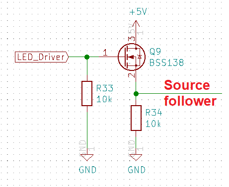
The main problem is that you haven't designed a level translator: -

enter image description here

It's a source follower and the voltage at the source will be approximately what is at the gate but about a volt lower in amplitude (MOSFET depending). It won't give a 5 volt PWM level translation. To do that you need the source connected to ground and a resistor from drain to 5 volts. This will produce what you need but, bear in mind it is an inverting stage so, 3.3 volts in produces 0 volts out and 0 volts in produces 5 volts out.

The PWM signal must have the driving ability to drive internal 500kΩ pull-up resistor. What does that mean?

It means that when you have correctly re-wired your MOSFET as per the above, the loading resistance of the ADJ input is 500 kΩ but, given that it is a pull-up internal resistance, it's of little consequence given that to to-be-added drain pull up resistor you would choose (about 10 kΩ) would swamp it.

The main problem is that you haven't designed a level translator: -

enter image description here

It's a source follower and the voltage at the source will be approximately what is at the gate but about a volt lower in amplitude (MOSFET depending). It won't give a 5 volt PWM level translation. To do that you need the source connected to ground and a resistor from drain to 5 volts. This will produce what you need but, bear in mind it is an inverting stage so, 3.3 volts in produces 0 volts out and 0 volts in produces 5 volts out.

The PWM signal must have the driving ability to drive internal 500kΩ pull-up resistor. What does that mean?

It means that when you have correctly re-wired your MOSFET as per the above, the loading resistance of the ADJ input is 500 kΩ but, given that it is a pull-up internal resistance, it's of little consequence given that the "to-be-added" drain pull up resistor (as per my earlier words) you would choose (about 10 kΩ) would swamp it.

Source Link
Andy aka
  • 473.1k
  • 29
  • 383
  • 839

The main problem is that you haven't designed a level translator: -

enter image description here

It's a source follower and the voltage at the source will be approximately what is at the gate but about a volt lower in amplitude (MOSFET depending). It won't give a 5 volt PWM level translation. To do that you need the source connected to ground and a resistor from drain to 5 volts. This will produce what you need but, bear in mind it is an inverting stage so, 3.3 volts in produces 0 volts out and 0 volts in produces 5 volts out.

The PWM signal must have the driving ability to drive internal 500kΩ pull-up resistor. What does that mean?

It means that when you have correctly re-wired your MOSFET as per the above, the loading resistance of the ADJ input is 500 kΩ but, given that it is a pull-up internal resistance, it's of little consequence given that to to-be-added drain pull up resistor you would choose (about 10 kΩ) would swamp it.