added 173 characters in body
Source Link
Andy aka
  • 473.1k
  • 29
  • 383
  • 839

clocked at 1MHz

Assuming that you might be interested in anything up to the 10th harmonic of 1 MHz (aAs a general rule of thumb when looking atinto data corruptions), on mis-terminated lines anything up to the 10th harmonic would be considered. So if the basic data rate is such that it looks like 1 MHz we might consider 10 MHz to be a good basis for analysis.

The wavelength of 10 MHz is 30 metres and, another the rule of thumb is that anythingany transmission line longer than about one-tenth of a wavelength is going tocould potentially be problematic if badly terminated. That's a line length of 3 metres.

What is the best way to handle this in your opinion?

Hence, 3 metresthere isn't really going to posebe a problem to either the data down the stub (30 cm) or the original data path (10 cm). If in doubt, connect to the stub via 1 kΩ resistors and use a differential amplifier to monitor the data signal.

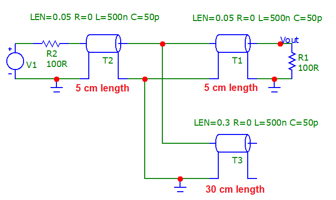
Simulation

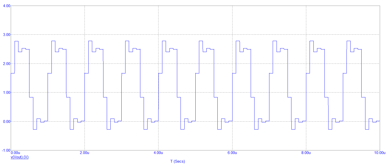
enter image description here

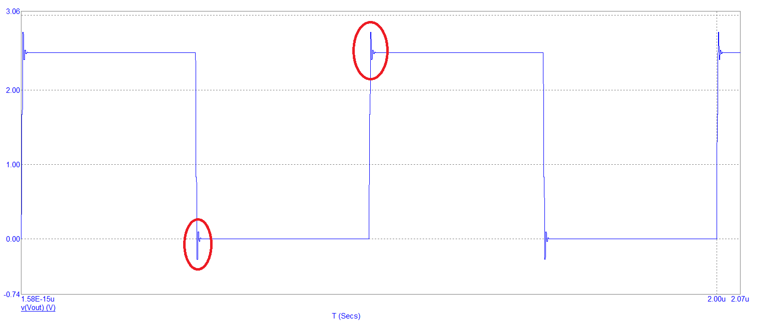
1 MHz output signal (Vout): -

enter image description here

I don't think the edge disruptions are significant for RS-422 integrity. If you do something like this: -

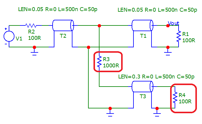
enter image description here

You'd be hard-pressed to see any degradation on your main RS-422 signal at all. And the monitor signal also looks good but, as expected is attenuated by 10:1.

Remember, my sims have used unbalanced signals and coax so, you'd need to split the 1 kΩ resistor into two 500 Ω resistors for proper RS-422.


As an afterthought...

If I made the monitor line 3 metres long and didn't use any resistors, I'd see this disruption on the main signal: -

enter image description here

It's still OK and wouldn't throw up any significant corruptions.

If I made the monitor line 10 metres long, the main signal is starting to look crappy: -

enter image description here

clocked at 1MHz

Assuming that you might be interested in anything up to the 10th harmonic of 1 MHz (a general rule of thumb when looking at data corruptions), the wavelength of 10 MHz is 30 metres and, another the rule of thumb is that anything longer than about one-tenth of a wavelength is going to potentially be problematic.

What is the best way to handle this in your opinion?

Hence, 3 metres isn't really going to pose a problem to either the data down the stub (30 cm) or the original data path (10 cm). If in doubt, connect to the stub via 1 kΩ resistors and use a differential amplifier to monitor the data signal.

Simulation

enter image description here

1 MHz output signal (Vout): -

enter image description here

I don't think the edge disruptions are significant for RS-422 integrity. If you do something like this: -

enter image description here

You'd be hard-pressed to see any degradation on your main RS-422 signal at all. And the monitor signal also looks good but, as expected is attenuated by 10:1.

Remember, my sims have used unbalanced signals and coax so, you'd need to split the 1 kΩ resistor into two 500 Ω resistors for proper RS-422.


As an afterthought...

If I made the monitor line 3 metres long and didn't use any resistors, I'd see this disruption on the main signal: -

enter image description here

It's still OK and wouldn't throw up any significant corruptions.

If I made the monitor line 10 metres long, the main signal is starting to look crappy: -
enter image description here

clocked at 1MHz

As a general rule of thumb when looking into data corruptions on mis-terminated lines anything up to the 10th harmonic would be considered. So if the basic data rate is such that it looks like 1 MHz we might consider 10 MHz to be a good basis for analysis.

The wavelength of 10 MHz is 30 metres and, another the rule of thumb is that any transmission line longer than about one-tenth of a wavelength could potentially be problematic if badly terminated. That's a line length of 3 metres.

What is the best way to handle this in your opinion?

Hence, there isn't really going to be a problem to either the data down the stub (30 cm) or the original data path (10 cm). If in doubt, connect to the stub via 1 kΩ resistors and use a differential amplifier to monitor the data signal.

Simulation

enter image description here

1 MHz output signal (Vout): -

enter image description here

I don't think the edge disruptions are significant for RS-422 integrity. If you do something like this: -

enter image description here

You'd be hard-pressed to see any degradation on your main RS-422 signal at all. And the monitor signal also looks good but, as expected is attenuated by 10:1.

Remember, my sims have used unbalanced signals and coax so, you'd need to split the 1 kΩ resistor into two 500 Ω resistors for proper RS-422.


As an afterthought...

If I made the monitor line 3 metres long and didn't use any resistors, I'd see this disruption on the main signal: -

enter image description here

It's still OK and wouldn't throw up any significant corruptions.

If I made the monitor line 10 metres long, the main signal is starting to look crappy: -
enter image description here

added 500 characters in body
Source Link
Andy aka
  • 473.1k
  • 29
  • 383
  • 839

clocked at 1MHz

Assuming that you might be interested in anything up to 10 harmonicsthe 10th harmonic of 1 MHz (a general rule of thumb when looking at data corruptions), the wavelength of 10 MHz is 30 metres and, another the rule of thumb is that anything longer than about one-tenth of a wavelength is going to potentially be problematic.

What is the best way to handle this in your opinion?

Hence, 3 metres isn't really going to pose a problem to either the data down the stub (30 cm) or the original data path (10 cm). If in doubt, connect to the stub via 1 kΩ resistors and use a differential amplifier to monitor the data signal.

Simulation

Simulation

enter image description here

1 MHz output signal (Vout): -

enter image description here

I don't think the edge disruptions are significant for RS-422 integrity. If you do something like this: -

enter image description here

You'd be hard-pressed to see any degradation on your main RS-422 signal at all. And the monitor signal also looks good but, as expected is attenuated by 10:1.

Remember, my sims have used unbalanced signals and coax so, you'd need to split the 1 kΩ resistor into two 500 Ω resistors for proper RS-422.


As an afterthought...

If I made the monitor line 3 metres long and didn't use any resistors, I'd see this disruption on the main signal: -

enter image description here

It's still OK and wouldn't throw up any significant corruptions.

If I made the monitor line 10 metres long, the main signal is starting to look crappy: -
enter image description here

clocked at 1MHz

Assuming that you might be interested in anything up to 10 harmonics of 1 MHz, the wavelength of 10 MHz is 30 metres and, the rule of thumb is that anything longer than about one-tenth of a wavelength is going to potentially be problematic.

What is the best way to handle this in your opinion?

Hence, 3 metres isn't really going to pose a problem to either the data down the stub (30 cm) or the original data path (10 cm). If in doubt, connect to the stub via 1 kΩ resistors and use a differential amplifier to monitor the data signal.

Simulation

enter image description here

1 MHz output signal (Vout): -

enter image description here

I don't think the edge disruptions are significant for RS-422 integrity. If you do something like this: -

enter image description here

You'd be hard-pressed to see any degradation on your main RS-422 signal at all. And the monitor signal also looks good but, as expected is attenuated by 10:1.

Remember, my sims have used unbalanced signals and coax so, you'd need to split the 1 kΩ resistor into two 500 Ω resistors for proper RS-422.

clocked at 1MHz

Assuming that you might be interested in anything up to the 10th harmonic of 1 MHz (a general rule of thumb when looking at data corruptions), the wavelength of 10 MHz is 30 metres and, another the rule of thumb is that anything longer than about one-tenth of a wavelength is going to potentially be problematic.

What is the best way to handle this in your opinion?

Hence, 3 metres isn't really going to pose a problem to either the data down the stub (30 cm) or the original data path (10 cm). If in doubt, connect to the stub via 1 kΩ resistors and use a differential amplifier to monitor the data signal.

Simulation

enter image description here

1 MHz output signal (Vout): -

enter image description here

I don't think the edge disruptions are significant for RS-422 integrity. If you do something like this: -

enter image description here

You'd be hard-pressed to see any degradation on your main RS-422 signal at all. And the monitor signal also looks good but, as expected is attenuated by 10:1.

Remember, my sims have used unbalanced signals and coax so, you'd need to split the 1 kΩ resistor into two 500 Ω resistors for proper RS-422.


As an afterthought...

If I made the monitor line 3 metres long and didn't use any resistors, I'd see this disruption on the main signal: -

enter image description here

It's still OK and wouldn't throw up any significant corruptions.

If I made the monitor line 10 metres long, the main signal is starting to look crappy: -
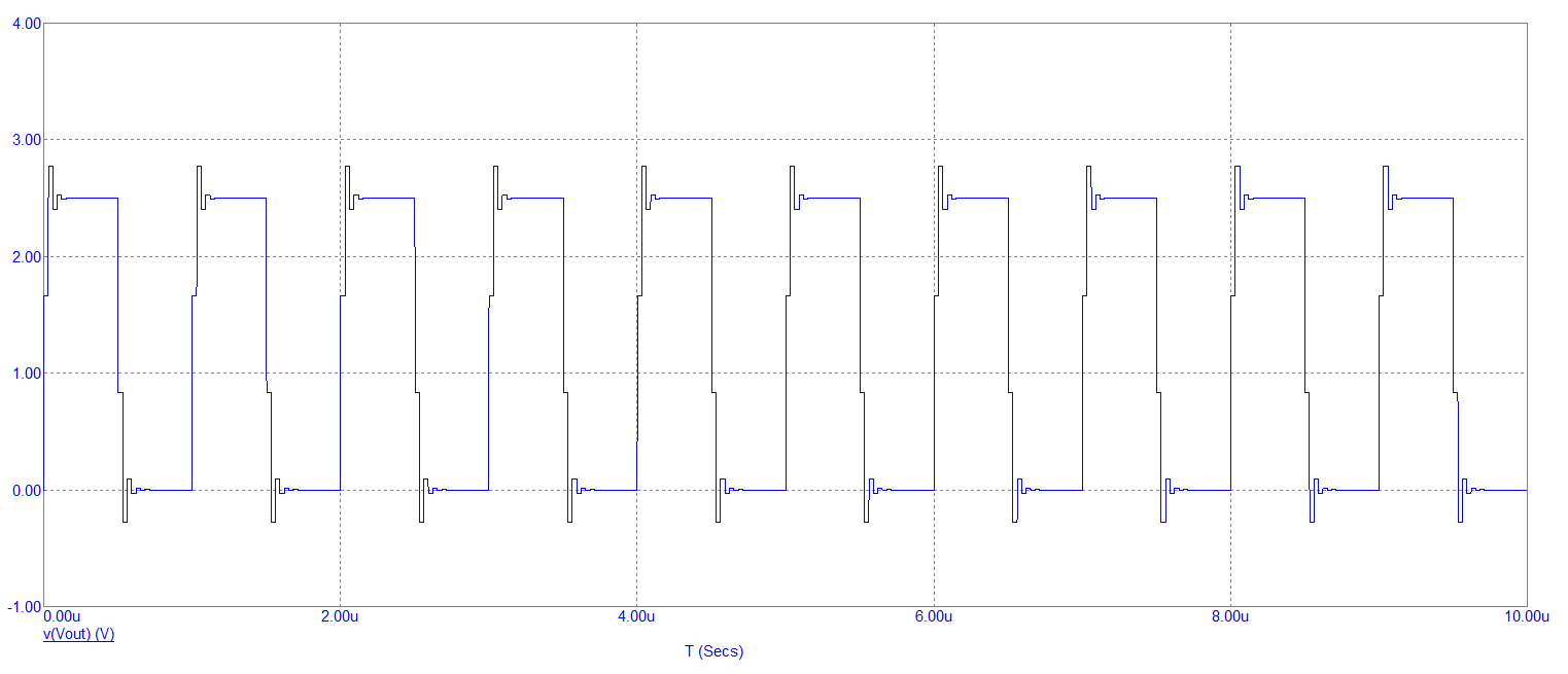
enter image description here

added 299 characters in body
Source Link
Andy aka
  • 473.1k
  • 29
  • 383
  • 839

clocked at 1MHz

Assuming that you might be interested in anything up to 10 harmonics of 1 MHz, the wavelength of 10 MHz is 30 metres and, the rule of thumb is that anything longer than about one-tenth of a wavelength is going to potentially be problematic.

What is the best way to handle this in your opinion?

Hence, 3 metres isn't really going to pose a problem to either the data down the stub (30 cm) or the original data path (10 cm). If in doubt, connect to the stub via 1 kΩ resistors and use a differential amplifier to monitor the data signal.

Simulation

enter image description here

1 MHz output signal (Vout): -

enter image description here

I don't think the edge disruptions are significant for RS-422 integrity. If you do something like this: -

enter image description here

You'd be hard-pressed to see any degradation on your main RS-422 signal at all. And the monitor signal also looks good but, as expected is attenuated by 10:1.

Remember, my sims have used unbalanced signals and coax so, you'd need to split the 1 kΩ resistor into two 500 Ω resistors for proper RS-422.

clocked at 1MHz

Assuming that you might be interested in anything up to 10 harmonics of 1 MHz, the wavelength of 10 MHz is 30 metres and, the rule of thumb is that anything longer than about one-tenth of a wavelength is going to potentially be problematic.

What is the best way to handle this in your opinion?

Hence, 3 metres isn't really going to pose a problem to either the data down the stub (30 cm) or the original data path (10 cm). If in doubt, connect to the stub via 1 kΩ resistors and use a differential amplifier to monitor the data signal.

Simulation

enter image description here

1 MHz output signal (Vout): -

enter image description here

I don't think the edge disruptions are significant for RS-422 integrity.

clocked at 1MHz

Assuming that you might be interested in anything up to 10 harmonics of 1 MHz, the wavelength of 10 MHz is 30 metres and, the rule of thumb is that anything longer than about one-tenth of a wavelength is going to potentially be problematic.

What is the best way to handle this in your opinion?

Hence, 3 metres isn't really going to pose a problem to either the data down the stub (30 cm) or the original data path (10 cm). If in doubt, connect to the stub via 1 kΩ resistors and use a differential amplifier to monitor the data signal.

Simulation

enter image description here

1 MHz output signal (Vout): -

enter image description here

I don't think the edge disruptions are significant for RS-422 integrity. If you do something like this: -

enter image description here

You'd be hard-pressed to see any degradation on your main RS-422 signal at all. And the monitor signal also looks good but, as expected is attenuated by 10:1.

Remember, my sims have used unbalanced signals and coax so, you'd need to split the 1 kΩ resistor into two 500 Ω resistors for proper RS-422.

added 299 characters in body
Source Link
Andy aka
  • 473.1k
  • 29
  • 383
  • 839
Loading
Source Link
Andy aka
  • 473.1k
  • 29
  • 383
  • 839
Loading