The power-on state of such a circuit is indeterminate and I'm surprised that this book you're referencing doesn't explain that.
While in the real world, circuits tend to initialize in a certain state MOST of the time, as you've seen, from time-to-time they don't. Why depends on many factors including power supply rise times, any residual charge in circuit elements from the last power-up, and just random processes.
The solution, if you need it to ALWAYS initialize to the same state, is to generate a power-on-reset using a suitable circuit. That will guarantee that it always comes on in the state you desire.
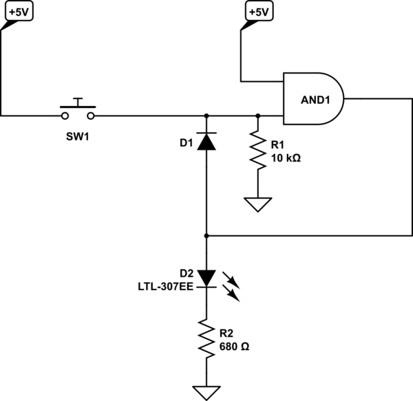
Your circuit is very confusingly drawn but is essentially this:

simulate this circuit – Schematic created using CircuitLab
This design relies on at least one of the inputs to the AND gate being LOW at power on so that the output will also be LOW. But with all digital logic parts there are "undefined" regions where the behavior is unspecified. At power-up this is where you are.
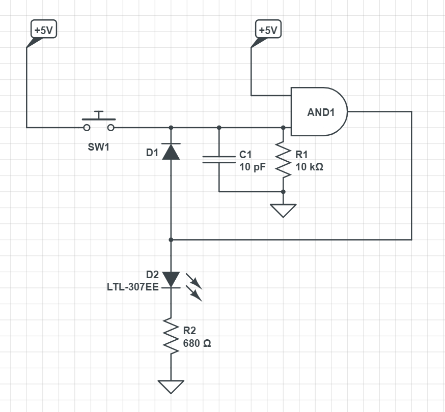
To address this you need to ENSURE that at least one of the inputs is low and one way to do that is by adding a capacitor in parallel with R1. The voltage across a capacitor will be 0V at power on and that will force the output of the AND gate to be a logic 0.
Try something like this. The value of C is not all that critical, try the 10pF and if that doesn't give you the behavior you want, experiment with some other values.

