added 76 characters in body
Source Link
Spehro 'speff' Pefhany
  • 422.6k
  • 23
  • 352
  • 950

I don't think battery power is very suitable for this circuit.

Just enough light to see- you may not need a Darlington at all, in fact you may be able to drive the LED directly from the module. There is apparently a 1K resistor in series (check that) and try just an LED to ground. A few mA into a modern bright LED produces quite a bit of light in a dark room. If you need more, a single transistor and a series resistor on the LED should be fine.

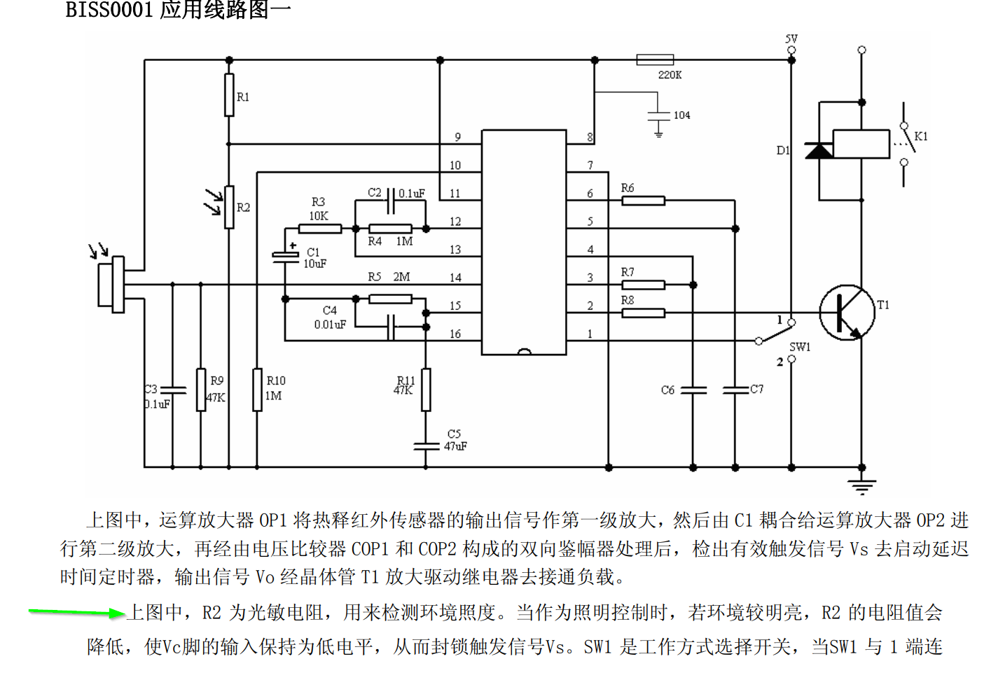
As far as using an LDR, if you refer to the datasheet for the Shenzhen Silvan BISS0001 chip used in these modules you will see the suggested circuit:

enter image description here

R2 is the LDR, R1 sets the threshold resistance. The light is disabled if the voltage at pin 9 is less than approximately 0.2Vcc. The modules appear to have pads for the LDR and a 1M resistor for R1, so you can locate the pads and add the LDR if it is not present. Check that the 1M resistor is present.

There are some English datasheets for the chip, but many of them seem to be incomplete.
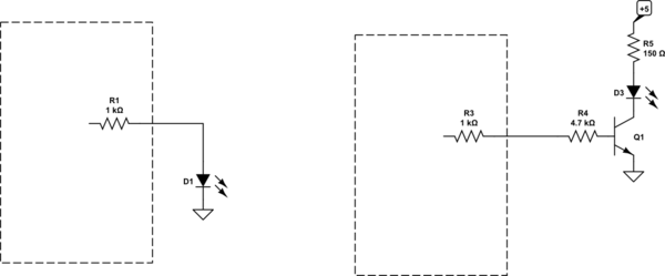
schematic

simulate this circuit – Schematic created using CircuitLab

Any of those transistors you mention will work in this circuit. I made the LED current around 13mA and the base current about 1/20 of that.

I don't think battery power is very suitable for this circuit.

Just enough light to see- you may not need a Darlington at all, in fact you may be able to drive the LED directly from the module. There is apparently a 1K resistor in series (check that) and try just an LED to ground. A few mA into a modern bright LED produces quite a bit of light in a dark room. If you need more, a single transistor and a series resistor on the LED should be fine.

As far as using an LDR, if you refer to the datasheet for the Shenzhen Silvan BISS0001 chip used in these modules you will see the suggested circuit:

enter image description here

R2 is the LDR, R1 sets the threshold resistance. The light is disabled if the voltage at pin 9 is less than approximately 0.2Vcc. The modules appear to have pads for the LDR and a 1M resistor for R1, so you can locate the pads and add the LDR if it is not present. Check that the 1M resistor is present.

There are some English datasheets for the chip, but many of them seem to be incomplete.

schematic

simulate this circuit – Schematic created using CircuitLab

Any of those transistors you mention will work in this circuit.

I don't think battery power is very suitable for this circuit.

Just enough light to see- you may not need a Darlington at all, in fact you may be able to drive the LED directly from the module. There is apparently a 1K resistor in series (check that) and try just an LED to ground. A few mA into a modern bright LED produces quite a bit of light in a dark room. If you need more, a single transistor and a series resistor on the LED should be fine.

As far as using an LDR, if you refer to the datasheet for the Shenzhen Silvan BISS0001 chip used in these modules you will see the suggested circuit:

enter image description here

R2 is the LDR, R1 sets the threshold resistance. The light is disabled if the voltage at pin 9 is less than approximately 0.2Vcc. The modules appear to have pads for the LDR and a 1M resistor for R1, so you can locate the pads and add the LDR if it is not present. Check that the 1M resistor is present.

There are some English datasheets for the chip, but many of them seem to be incomplete.

schematic

simulate this circuit – Schematic created using CircuitLab

Any of those transistors you mention will work in this circuit. I made the LED current around 13mA and the base current about 1/20 of that.

added 334 characters in body
Source Link
Spehro 'speff' Pefhany
  • 422.6k
  • 23
  • 352
  • 950

I don't think battery power is very suitable for this circuit.

Just enough light to see- you may not need a Darlington at all, in fact you may be able to drive the LED directly from the module. There is apparently a 1K resistor in series (check that) and try just an LED to ground. A few mA into a modern bright LED produces quite a bit of light in a dark room. If you need more, a single transistor and a series resistor on the LED should be fine.

As far as using an LDR, if you refer to the datasheet for the Shenzhen Silvan BISS0001 chip used in these modules you will see the suggested circuit:

enter image description here

R2 is the LDR, R1 sets the threshold resistance. The light is disabled if the voltage at pin 9 is less than approximately 0.2Vcc. The modules appear to have pads for the LDR and a 1M resistor for R1, so you can locate the pads and add the LDR if it is not present. Check that the 1M resistor is present.

There are some English datasheets for the chip, but many of them seem to be incomplete.

schematic

simulate this circuit – Schematic created using CircuitLab

Any of those transistors you mention will work in this circuit.

I don't think battery power is very suitable for this circuit.

Just enough light to see- you may not need a Darlington at all, in fact you may be able to drive the LED directly from the module. There is apparently a 1K resistor in series (check that) and try just an LED to ground. A few mA into a modern bright LED produces quite a bit of light in a dark room. If you need more, a single transistor and a series resistor on the LED should be fine.

As far as using an LDR, if you refer to the datasheet for the Shenzhen Silvan BISS0001 chip used in these modules you will see the suggested circuit:

enter image description here

R2 is the LDR, R1 sets the threshold resistance. The light is disabled if the voltage at pin 9 is less than approximately 0.2Vcc.

There are some English datasheets for the chip, but many of them seem to be incomplete.

I don't think battery power is very suitable for this circuit.

Just enough light to see- you may not need a Darlington at all, in fact you may be able to drive the LED directly from the module. There is apparently a 1K resistor in series (check that) and try just an LED to ground. A few mA into a modern bright LED produces quite a bit of light in a dark room. If you need more, a single transistor and a series resistor on the LED should be fine.

As far as using an LDR, if you refer to the datasheet for the Shenzhen Silvan BISS0001 chip used in these modules you will see the suggested circuit:

enter image description here

R2 is the LDR, R1 sets the threshold resistance. The light is disabled if the voltage at pin 9 is less than approximately 0.2Vcc. The modules appear to have pads for the LDR and a 1M resistor for R1, so you can locate the pads and add the LDR if it is not present. Check that the 1M resistor is present.

There are some English datasheets for the chip, but many of them seem to be incomplete.

schematic

simulate this circuit – Schematic created using CircuitLab

Any of those transistors you mention will work in this circuit.

Source Link
Spehro 'speff' Pefhany
  • 422.6k
  • 23
  • 352
  • 950

I don't think battery power is very suitable for this circuit.

Just enough light to see- you may not need a Darlington at all, in fact you may be able to drive the LED directly from the module. There is apparently a 1K resistor in series (check that) and try just an LED to ground. A few mA into a modern bright LED produces quite a bit of light in a dark room. If you need more, a single transistor and a series resistor on the LED should be fine.

As far as using an LDR, if you refer to the datasheet for the Shenzhen Silvan BISS0001 chip used in these modules you will see the suggested circuit:

enter image description here

R2 is the LDR, R1 sets the threshold resistance. The light is disabled if the voltage at pin 9 is less than approximately 0.2Vcc.

There are some English datasheets for the chip, but many of them seem to be incomplete.