deleted 6 characters in body
Source Link
JRE
  • 73.6k
  • 10
  • 112
  • 195

HaveI have a circuit with IGBTs which charges and discharges two different capacitor lines as a function of the voltage. i.e. when a voltage is detected below 160V, Q1 charges C1 and when a voltage over 160V and below 500V is detected, Q2 charges C2, and all voltages over 500V and up to 1000V are charged with Q3 and C2 and C3 in series. 

After charging, the capacitors are discharged by R1 and R3 depending on which circuit was used. 

All IGBTs are beign driven with ana UCC21520 driver by means of a microcontroller. Isolated power supplies are obtained withfrom an NMK1515SC DcDcDCDC converter with 3000Vrms isolation during 1 second.
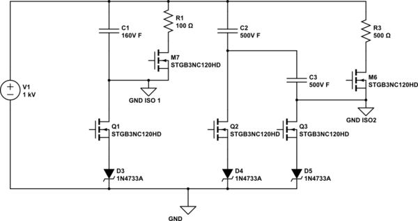
schematic

simulate this circuit – Schematic created using CircuitLab

The problem comes whenis that charging at high voltages (over 800V typically,) that Q1 is failing, going into short-circuit and therefore C1 gets exposed to 800V and ends up exploding. 

Sometimes it also happens in Q2, although less frequently. I suspect various things could be happening but not 100% in any of them and not even sure if it could be some other thing:

  • When Q3 is closed V_CE of Q1 changes from 850 to 0V and then slowly back to 850V with the charging of C2 and C3. This without Q1 beign activated and could be the cause of the failue of Q1.

    When Q3 is closed V_CE of Q1 changes from 850 to 0V and then slowly back to 850V with the charging of C2 and C3. This without Q1 beign activated and could be the cause of the failue of Q1.
  • Right now not using a resistor betwenn the IGBT driver and the IGBT gate which could cause voltage overshoot and cause the IGBT to fail. But this should occur on the IGBT beign triggered and not another one.

    Right now not using a resistor betwenn the IGBT driver and the IGBT gate which could cause voltage overshoot and cause the IGBT to fail. But this should occur on the IGBT beign triggered and not another one.
  • Maybe IGBT model is not the most appropiate.

    Maybe IGBT model is not the most appropiate.

Any other ideas would be very much appreciated

IGBT datasheet:.

https://www.st.com/content/ccc/resource/technical/document/datasheet/group2/5a/39/10/6a/d6/fe/44/bc/CD00047515/files/CD00047515.pdf/jcr:content/translations/en.CD00047515IGBT datasheet.pdf

IGBT driver circuit:

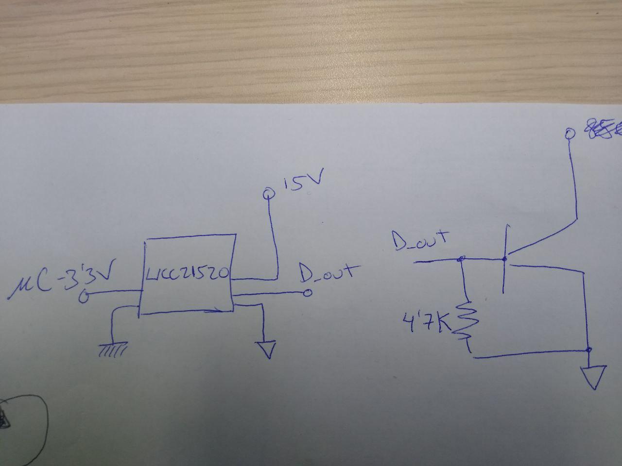
enter image description hereenter image description here

Have a circuit with IGBTs which charges and discharges two different capacitor lines as a function of the voltage. i.e. when a voltage is detected below 160V, Q1 charges C1 and when a voltage over 160V and below 500V is detected, Q2 charges C2, and all voltages over 500V and up to 1000V are charged with Q3 and C2 and C3 in series. After charging, the capacitors are discharged by R1 and R3 depending on which circuit was used. All IGBTs are beign driven with an UCC21520 driver by means of a microcontroller. Isolated power supplies are obtained with an NMK1515SC DcDc converter with 3000Vrms isolation during 1 second.

schematic

simulate this circuit – Schematic created using CircuitLab

The problem comes when charging at high voltages (over 800V typically) that Q1 is failing, going into short-circuit and therefore C1 gets exposed to 800V and ends up exploding. Sometimes it also happens in Q2, although less frequently. I suspect various things could be happening but not 100% in any of them and not even sure if it could be some other thing:

  • When Q3 is closed V_CE of Q1 changes from 850 to 0V and then slowly back to 850V with the charging of C2 and C3. This without Q1 beign activated and could be the cause of the failue of Q1.

  • Right now not using a resistor betwenn the IGBT driver and the IGBT gate which could cause voltage overshoot and cause the IGBT to fail. But this should occur on the IGBT beign triggered and not another one.

  • Maybe IGBT model is not the most appropiate.

Any other ideas would be very much appreciated

IGBT datasheet:

https://www.st.com/content/ccc/resource/technical/document/datasheet/group2/5a/39/10/6a/d6/fe/44/bc/CD00047515/files/CD00047515.pdf/jcr:content/translations/en.CD00047515.pdf

IGBT driver circuit:

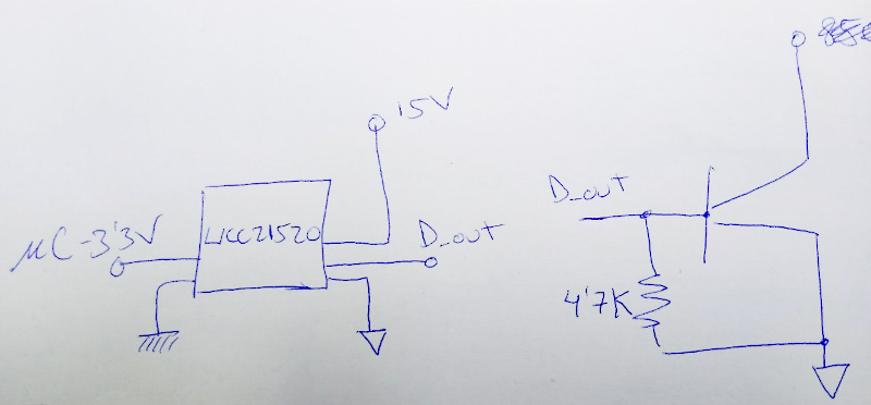
enter image description here

I have a circuit with IGBTs which charges and discharges two different capacitor lines as a function of the voltage. i.e. when a voltage is detected below 160V, Q1 charges C1 and when a voltage over 160V and below 500V is detected, Q2 charges C2, and all voltages over 500V and up to 1000V are charged with Q3 and C2 and C3 in series. 

After charging, the capacitors are discharged by R1 and R3 depending on which circuit was used. 

All IGBTs are driven with a UCC21520 driver by means of a microcontroller. Isolated power supplies are obtained from an NMK1515SC DCDC converter with 3000Vrms isolation during 1 second.

schematic

simulate this circuit – Schematic created using CircuitLab

The problem is that charging at high voltages (over 800V typically,) Q1 is failing, going into short-circuit and therefore C1 gets exposed to 800V and ends up exploding. 

Sometimes it also happens in Q2, although less frequently. I suspect various things could be happening but not 100% in any of them and not even sure if it could be some other thing:

  • When Q3 is closed V_CE of Q1 changes from 850 to 0V and then slowly back to 850V with the charging of C2 and C3. This without Q1 beign activated and could be the cause of the failue of Q1.
  • Right now not using a resistor betwenn the IGBT driver and the IGBT gate which could cause voltage overshoot and cause the IGBT to fail. But this should occur on the IGBT beign triggered and not another one.
  • Maybe IGBT model is not the most appropiate.

Any other ideas would be very much appreciated.

IGBT datasheet.

IGBT driver circuit:

enter image description here

added 115 characters in body
Source Link

Have a circuit with IGBTs which charges and discharges two different capacitor lines as a function of the voltage. i.e. when a voltage is detected below 160V, Q1 charges C1 and when a voltage over 160V and below 500V is detected, Q2 charges C2, and all voltages over 500V and up to 1000V are charged with Q3 and C2 and C3 in series. After charging, the capacitors are discharged by R1 and R3 depending on which circuit was used. All IGBTs are beign driven with an UCC21520 driver by means of a microcontroller. Isolated power supplies are obtained with an NMK1515SC DcDc converter with 3000Vrms isolation during 1 second.

schematic

simulate this circuit – Schematic created using CircuitLab

The problem comes when charging at high voltages (over 800V typically) that Q1 is failing, going into short-circuit and therefore C1 gets exposed to 800V and ends up exploding. Sometimes it also happens in Q2, although less frequently. I suspect various things could be happening but not 100% in any of them and not even sure if it could be some other thing:

  • When Q3 is closed V_CE of Q1 changes from 850 to 0V and then slowly back to 850V with the charging of C2 and C3. This without Q1 beign activated and could be the cause of the failue of Q1.

  • Right now not using a resistor betwenn the IGBT driver and the IGBT gate which could cause voltage overshoot and cause the IGBT to fail. But this should occur on the IGBT beign triggered and not another one.

  • Maybe IGBT model is not the most appropiate.

Any other ideas would be very much appreciated

IGBT datasheet:

https://www.st.com/content/ccc/resource/technical/document/datasheet/group2/5a/39/10/6a/d6/fe/44/bc/CD00047515/files/CD00047515.pdf/jcr:content/translations/en.CD00047515.pdf

IGBT driver circuit:

enter image description here

Have a circuit with IGBTs which charges and discharges two different capacitor lines as a function of the voltage. i.e. when a voltage is detected below 160V, Q1 charges C1 and when a voltage over 160V and below 500V is detected, Q2 charges C2, and all voltages over 500V and up to 1000V are charged with Q3 and C2 and C3 in series. After charging, the capacitors are discharged by R1 and R3 depending on which circuit was used. All IGBTs are beign driven with an UCC21520 driver by means of a microcontroller. Isolated power supplies are obtained with an NMK1515SC DcDc converter with 3000Vrms isolation during 1 second.

schematic

simulate this circuit – Schematic created using CircuitLab

The problem comes when charging at high voltages (over 800V typically) that Q1 is failing, going into short-circuit and therefore C1 gets exposed to 800V and ends up exploding. Sometimes it also happens in Q2, although less frequently. I suspect various things could be happening but not 100% in any of them and not even sure if it could be some other thing:

  • When Q3 is closed V_CE of Q1 changes from 850 to 0V and then slowly back to 850V with the charging of C2 and C3. This without Q1 beign activated and could be the cause of the failue of Q1.

  • Right now not using a resistor betwenn the IGBT driver and the IGBT gate which could cause voltage overshoot and cause the IGBT to fail. But this should occur on the IGBT beign triggered and not another one.

  • Maybe IGBT model is not the most appropiate.

Any other ideas would be very much appreciated

IGBT datasheet:

https://www.st.com/content/ccc/resource/technical/document/datasheet/group2/5a/39/10/6a/d6/fe/44/bc/CD00047515/files/CD00047515.pdf/jcr:content/translations/en.CD00047515.pdf

IGBT driver circuit:

enter image description here

added 195 characters in body
Source Link

Have a circuit with IGBTs which charges and discharges two different capacitor lines as a function of the voltage. i.e. when a voltage is detected below 160V, Q1 charges C1 and when a voltage over 160V and below 500V is detected, Q2 charges C2, and all voltages over 500V and up to 1000V are charged with Q3 and C2 and C3 in series. After charging, the capacitors are discharged by R1 and R3 depending on which circuit was used. All IGBTs are beign driven with an UCC21520 driver by means of a microcontroller. Isolated power supplies are obtained with an NMK1515SC DcDc converter with 3000Vrms isolation during 1 second.

schematic

simulate this circuit – Schematic created using CircuitLab

The problem comes when charging at high voltages (over 800V typically) that Q1 is failing, going into short-circuit and therefore C1 gets exposed to 800V and ends up exploding. Sometimes it also happens in Q2, although less frequently. I suspect various things could be happening but not 100% in any of them and not even sure if it could be some other thing:

  • When Q3 is closed V_CE of Q1 changes from 850 to 0V and then slowly back to 850V with the charging of C2 and C3. This without Q1 beign activated and could be the cause of the failue of Q1.

  • Right now not using a resistor betwenn the IGBT driver and the IGBT gate which could cause voltage overshoot and cause the IGBT to fail. But this should occur on the IGBT beign triggered and not another one.

  • Maybe IGBT model is not the most appropiate.

Any other ideas would be very much appreciated

IGBT datasheet:

https://www.st.com/content/ccc/resource/technical/document/datasheet/group2/5a/39/10/6a/d6/fe/44/bc/CD00047515/files/CD00047515.pdf/jcr:content/translations/en.CD00047515.pdf

Have a circuit with IGBTs which charges and discharges two different capacitor lines as a function of the voltage. i.e. when a voltage is detected below 160V, Q1 charges C1 and when a voltage over 160V and below 500V is detected, Q2 charges C2, and all voltages over 500V and up to 1000V are charged with Q3 and C2 and C3 in series. After charging, the capacitors are discharged by R1 and R3 depending on which circuit was used. All IGBTs are beign driven with an UCC21520 driver by means of a microcontroller. Isolated power supplies are obtained with an NMK1515SC DcDc converter with 3000Vrms isolation during 1 second.

schematic

simulate this circuit – Schematic created using CircuitLab

The problem comes when charging at high voltages (over 800V typically) that Q1 is failing, going into short-circuit and therefore C1 gets exposed to 800V and ends up exploding. Sometimes it also happens in Q2, although less frequently. I suspect various things could be happening but not 100% in any of them and not even sure if it could be some other thing:

  • When Q3 is closed V_CE of Q1 changes from 850 to 0V and then slowly back to 850V with the charging of C2 and C3. This without Q1 beign activated and could be the cause of the failue of Q1.

  • Right now not using a resistor betwenn the IGBT driver and the IGBT gate which could cause voltage overshoot and cause the IGBT to fail. But this should occur on the IGBT beign triggered and not another one.

  • Maybe IGBT model is not the most appropiate.

Any other ideas would be very much appreciated

IGBT datasheet:

https://www.st.com/content/ccc/resource/technical/document/datasheet/group2/5a/39/10/6a/d6/fe/44/bc/CD00047515/files/CD00047515.pdf/jcr:content/translations/en.CD00047515.pdf

Source Link
Loading