Tweeted twitter.com/StackElectronix/status/1383526078791049220
Became Hot Network Question
added 173 characters in body
Source Link
JRE
  • 73.5k
  • 10
  • 112
  • 194

Recently, I tried to simulate an example CCcommon collector amplifier given in the book Electronic DevicesElectronic Devices by Floyd. 

The circuit depicted in the book is:

enter image description here

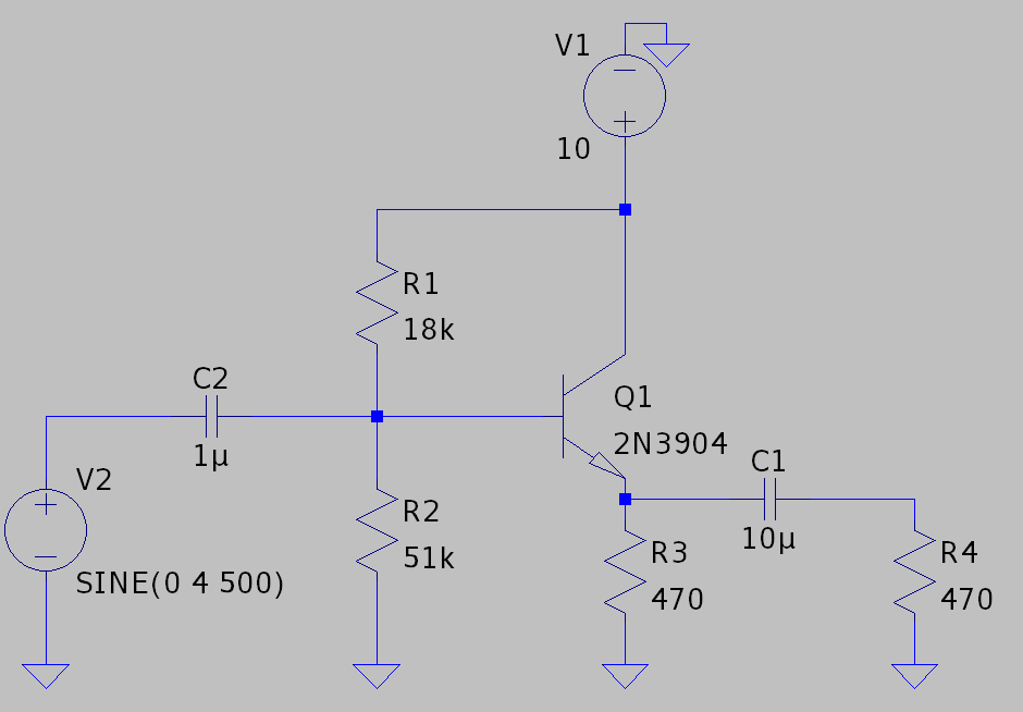
I used LTSpiceLTspice with Transienttransient analysis to implement and simulate the circuit:

enter image description here

Just after checking the input and output waveforms, I discovered the circuit has several problems. First, the output voltage signal gets clipped (or whatever the right term is) on the bottom part:

Green wave is the input (probed just after the sinusoidal input source). Blue wave is the output (probed just before the R4)

Green wave is the input (probed just after the sinusoidal input source). Blue wave is the output (probed just before R4.)

Second, there is some kind of "weirdness" in the input current:

enter image description here

On the other hand, if I decrease the input voltage to 3VP, those problems disappear, namely, I get a good output voltage and no irregularities in the input current. 

What is the problem with this circuit? For the input signal of 4VP, should not 10 VCC be enough for the amplifier? How can I design a CC amplifier circuit that has a better output swing? What is the problem with the input current? Should not the current, in any case, be sinusoidal? How it gets this "weird" shape?

  • For the input signal of 4VP, should not 10 VCC be enough for the amplifier?
  • How can I design a CC amplifier circuit that has a better output swing?
  • What is the problem with the input current?
  • Should not the current, in any case, be sinusoidal?
  • How does it get this "weird" shape?

I believe these questions are interrelated, so decided to ask them in just one post. 

I am also pretty new to electronics and analog circuit design, so maybe there is something important I missmissed in the analysis of transistor amplifier circuits.

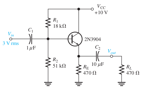
Recently, I tried to simulate an example CC amplifier given in the book Electronic Devices by Floyd. The circuit depicted in the book is:

enter image description here

I used LTSpice with Transient analysis to implement and simulate the circuit:

enter image description here

Just after checking the input and output waveforms, I discovered the circuit has several problems. First, the output voltage signal gets clipped (or whatever the right term is) on the bottom part:

Green wave is the input (probed just after the sinusoidal input source). Blue wave is the output (probed just before the R4)

Second, there is some kind of "weirdness" in the input current:

enter image description here

On the other hand, if I decrease the input voltage to 3VP, those problems disappear, namely, I get a good output voltage and no irregularities in the input current. What is the problem with this circuit? For the input signal of 4VP, should not 10 VCC be enough for the amplifier? How can I design a CC amplifier circuit that has a better output swing? What is the problem with the input current? Should not the current, in any case, be sinusoidal? How it gets this "weird" shape? I believe these questions are interrelated, so decided to ask them in just one post. I am also pretty new to electronics and analog circuit design, so maybe there is something important I miss in the analysis of transistor amplifier circuits.
I tried to simulate an example common collector amplifier given in the book Electronic Devices by Floyd. 

The circuit depicted in the book is:

enter image description here

I used LTspice with transient analysis to implement and simulate the circuit:

enter image description here

Just after checking the input and output waveforms, I discovered the circuit has several problems. First, the output voltage signal gets clipped (or whatever the right term is) on the bottom part:

Green wave is the input (probed just after the sinusoidal input source). Blue wave is the output (probed just before the R4)

Green wave is the input (probed just after the sinusoidal input source). Blue wave is the output (probed just before R4.)

Second, there is some kind of "weirdness" in the input current:

enter image description here

On the other hand, if I decrease the input voltage to 3VP, those problems disappear, namely, I get a good output voltage and no irregularities in the input current. 

What is the problem with this circuit?

  • For the input signal of 4VP, should not 10 VCC be enough for the amplifier?
  • How can I design a CC amplifier circuit that has a better output swing?
  • What is the problem with the input current?
  • Should not the current, in any case, be sinusoidal?
  • How does it get this "weird" shape?

I believe these questions are interrelated, so decided to ask them in just one post. 

I am also pretty new to electronics and analog circuit design, so maybe there is something important I missed in the analysis of transistor amplifier circuits.

Source Link
Fuad Zadeh
  • 165
  • 1
  • 7

How to design a good common-collector amplifier?

Recently, I tried to simulate an example CC amplifier given in the book Electronic Devices by Floyd. The circuit depicted in the book is:

enter image description here

I used LTSpice with Transient analysis to implement and simulate the circuit:

enter image description here

Just after checking the input and output waveforms, I discovered the circuit has several problems. First, the output voltage signal gets clipped (or whatever the right term is) on the bottom part:

Green wave is the input (probed just after the sinusoidal input source). Blue wave is the output (probed just before the R4)

Second, there is some kind of "weirdness" in the input current:

enter image description here

On the other hand, if I decrease the input voltage to 3VP, those problems disappear, namely, I get a good output voltage and no irregularities in the input current. What is the problem with this circuit? For the input signal of 4VP, should not 10 VCC be enough for the amplifier? How can I design a CC amplifier circuit that has a better output swing? What is the problem with the input current? Should not the current, in any case, be sinusoidal? How it gets this "weird" shape? I believe these questions are interrelated, so decided to ask them in just one post. I am also pretty new to electronics and analog circuit design, so maybe there is something important I miss in the analysis of transistor amplifier circuits.