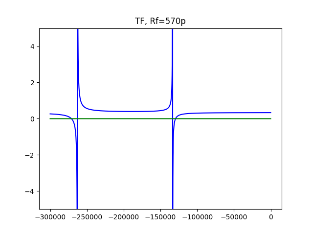
The authors of Analog's article Practical Techniques to Avoid Instability Due to Capacitive Loading correctly compute TF poles and zeroes of the inloop compensation circuit feedback, applying OCTC. What they do in error is that they use a pole zero cancellation method for computing the feedback capacitor value required to flatten the transfer function best.
The OCTC method used in the Practical Techniques.. article is an approximate analysis techniques used in electronic circuit design to determine the corner frequency of complex circuits (citing the Wikipedia article on OCTC). As for the criterion of the approximation validity, the Wikipedia article states that a fairly large ratio of \$τ_1/τ_2\$ is needed for accuracy.
From the Wiki article formulas one can see that the time constants \$τ_1, τ_2\$ are the inverse (and negated) values of the transfer function poles, $$ s_{1,2} = -1/τ_{1,2} $$ The article uses an imaginary variable \$j\omega\$, I use a Laplace domain variable \$s\$, which is more convenient for an analysis of capacitive circuits with their pure real poles/zeros.
For the circuit of the Practical Techniques.. article, the time constant ratio value is about two, so OCTC gives only coarse estimation. The pole and zero cancellation method, when used for calculation of the component values, solves some kind of an inverse problem and sowhich is not well conditioned as it is very sensitive to the precision of pole and zero values. For illustration of potential complications, look atnotice the transfer functionuncertainty of the feedback circuit discussed in the Practical Techniques.. article withTF zero positions easily shiftedlocated at potentially gradual TF curve slopes.
Here, TF is computed for the inloop frequency compensation circuit with component values Rout = 50, Rx = 25, Rf = 20K, Rin = 10K, CL = 100n and Cf = 570p. Pole/zero pair values are -262839/-271047 and -133494/-129452. When Cf value tends to 561.096382331p, the pole values tend to -267000 and -133500, and the transfer function tend to become constant. Try and compare this exact pole/zero values with those computed by the formulas of the Practical Techniques.. article.
You can find an exact solution for the inloop frequency compensation feedback circuit in my answer to the electronics.SE question Understanding on frequency compensation on driving capacitive loads with an op-amp.


