edited body
Source Link
Andy aka
  • 473.1k
  • 29
  • 383
  • 839

But from 12.8v to 13v the relay buzzes on and off.

The problem is likely this; when the relay is activated the current drawn from the solar panel causes a drop in its supply voltage and this then causes the LM393 to deactivate the relay. That deactivation means less current from the solar panel hence the voltage rises a bit and, the LM393 then retriggers and you are going round in a circle until the voltage rises sufficiently on the panel that it doesn't drop below the LM393 threshold voltage when the relay gets activated.

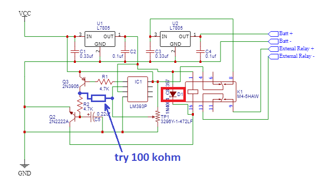
As others have pointed out, D1 appears to be the wrong way round in your schematic: -

enter image description hereenter image description here

I've also added a resistor that creates hysteresis and the value of 100 kΩ might be enough to avoid the problem of the relay buzzing in that when the output of the LM393 switches, it adjusts the target threshold for the comparator a bit.

Please try and use the right symbol for the LM393 rather than just a box with connections and no pin numbers. It would also help if you positions BJTs so that they were more logically drawn (Q2 for instance).

But from 12.8v to 13v the relay buzzes on and off.

The problem is likely this; when the relay is activated the current drawn from the solar panel causes a drop in its supply voltage and this then causes the LM393 to deactivate the relay. That deactivation means less current from the solar panel hence the voltage rises a bit and, the LM393 then retriggers and you are going round in a circle until the voltage rises sufficiently on the panel that it doesn't drop below the LM393 threshold voltage when the relay gets activated.

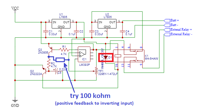
As others have pointed out, D1 appears to be the wrong way round in your schematic: -

enter image description here

I've also added a resistor that creates hysteresis and the value of 100 kΩ might be enough to avoid the problem of the relay buzzing in that when the output of the LM393 switches, it adjusts the target threshold for the comparator a bit.

Please try and use the right symbol for the LM393 rather than just a box with connections and no pin numbers. It would also help if you positions BJTs so that they were more logically drawn (Q2 for instance).
But from 12.8v to 13v the relay buzzes on and off.

The problem is likely this; when the relay is activated the current drawn from the solar panel causes a drop in its supply voltage and this then causes the LM393 to deactivate the relay. That deactivation means less current from the solar panel hence the voltage rises a bit and, the LM393 then retriggers and you are going round in a circle until the voltage rises sufficiently on the panel that it doesn't drop below the LM393 threshold voltage when the relay gets activated.

As others have pointed out, D1 appears to be the wrong way round in your schematic: -

enter image description here

I've also added a resistor that creates hysteresis and the value of 100 kΩ might be enough to avoid the problem of the relay buzzing in that when the output of the LM393 switches, it adjusts the target threshold for the comparator a bit.

Please try and use the right symbol for the LM393 rather than just a box with connections and no pin numbers. It would also help if you positions BJTs so that they were more logically drawn (Q2 for instance).
added 244 characters in body
Source Link
Andy aka
  • 473.1k
  • 29
  • 383
  • 839

But from 12.8v to 13v the relay buzzes on and off.

The problem is likely this; when the relay is activated the current drawn from the solar panel causes a drop in its supply voltage and this then causes the LM393 to deactivate the relay. That deactivation means less current from the solar panel hence the voltage rises a bit and, the LM393 then retriggers and you are going round in a circle until the voltage rises sufficiently on the panel that it doesn't drop below the LM393 threshold voltage when the relay gets activated.

As others have pointed out, D1 appears to be the wrong way round in your schematic: -

enter image description hereenter image description here

I've also added a resistor that creates hysteresis and the value of 100 kΩ might be enough to avoid the problem of the relay buzzing in that when the output of the LM393 switches, it adjusts the target threshold for the comparator a bit.

Please try and use the right symbol for the LM393 rather than just a box with connections and no pin numbers. It would also help if you positions BJTs so that they were more logically drawn (Q2 for instance).

But from 12.8v to 13v the relay buzzes on and off.

The problem is likely this; when the relay is activated the current drawn from the solar panel causes a drop in its supply voltage and this then causes the LM393 to deactivate the relay. That deactivation means less current from the solar panel hence the voltage rises a bit and, the LM393 then retriggers and you are going round in a circle until the voltage rises sufficiently on the panel that it doesn't drop below the LM393 threshold voltage when the relay gets activated.

As others have pointed out, D1 appears to be the wrong way round in your schematic: -

enter image description here

I've also added a resistor that creates hysteresis and the value of 100 kΩ might be enough to avoid the problem of the relay buzzing in that when the output of the LM393 switches, it adjusts the target threshold for the comparator a bit.

Please try and use the right symbol for the LM393 rather than just a box with connections and no pin numbers. It would also help if you positions BJTs so that they were more logically drawn (Q2 for instance).

Source Link
Andy aka
  • 473.1k
  • 29
  • 383
  • 839

But from 12.8v to 13v the relay buzzes on and off.

The problem is likely this; when the relay is activated the current drawn from the solar panel causes a drop in its supply voltage and this then causes the LM393 to deactivate the relay. That deactivation means less current from the solar panel hence the voltage rises a bit and, the LM393 then retriggers and you are going round in a circle until the voltage rises sufficiently on the panel that it doesn't drop below the LM393 threshold voltage when the relay gets activated.

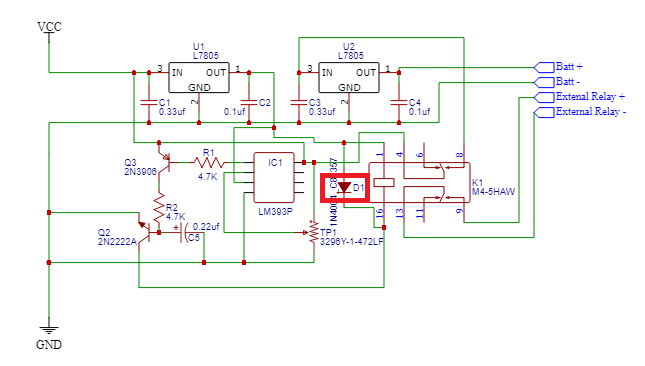
As others have pointed out, D1 appears to be the wrong way round in your schematic: -

enter image description here

Please try and use the right symbol for the LM393 rather than just a box with connections and no pin numbers. It would also help if you positions BJTs so that they were more logically drawn (Q2 for instance).