A so-called indirect energy transfer converter cannot operate without load. This is true for a boost, buck-boost or flyback converter. This is because at each turn-on event, you store energy in the primary inductance of the flyback transformer and, at the switch opening, this energy has to go somewhere. If there is no load to absorb the power generated cycle-by-cycle, then the output voltage increases until something breaks. It can be the output capacitor venting out, the primary-side MOSFET blowing up because you exceed its \$BV_{DSS}\$ or the secondary-side diode whose breakdown voltage is violated. This is a typical case when the converter runs in open-loop, for instance if the optocoupler is destroyed.
In a true no-load condition, the converter will try to reduce its duty ratio as much as it can. However, in current-mode control which is the most popular control method, the minimum pulse width is constrained to the sum \$t_{prop}+t_{LEB}\$ which can be as high as 150 ns + 250 ns = 400 ns. \$t_{prop}\$ represents the time to shut down the power switch when the CS comparator detects the peak value and \$t_{prop}\$\$t_{LEB}\$ designates the leading-edge blanking time needed to cleanse the current spike. For a 100-kHz converter, it can amount to a minimum duty ratio of 0.4/10 = 4% which is not that high but still large. So if a converter is left in a no-load condition with such a minimum duty ratio, what is going on? Well, if you are lucky enough that the natural output load (the optocoupler bias current, the resistive divider, a potential bleeder) absorbs the energy in this mode, you are safe. If not, then the voltage will inexorably increase, going back to the situation I described before.
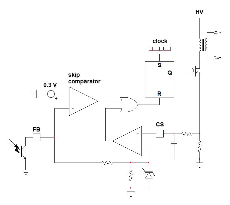
Some controllers can go down to true 0% duty ratio and the venerable UC384x is one of them. For the other ones, one very simple mechanism is called skip cycle. An extra comparator is installed in the circuit, observing the feedback voltage (FB). When the feedback voltage is high enough, the skip comparator is silent. When the FB voltage decreases too much (300 mV typically) and tends to impose too low a peak current, approaching the minimum pulse width, then the skip comparator kicks in and resets the PWM latch, stopping all pulses:
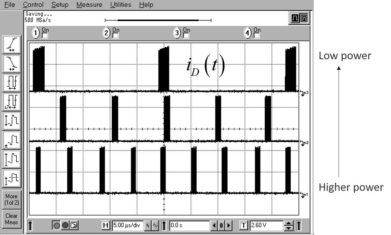
This technique is now very popular and found in almost all ac-dc offline controllers. New techniques have emerged to reduce the acoustic noise as pulse bunches can excite the transformer which becomes a transducer. Typical operating waveforms are shown below:
With this technique, you can safely operate down to 0 A and reduce the standby power to the lowest value, typically below 100 mW at a 230-V rms voltage.


