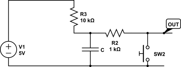
simulate this circuit – Schematic created using CircuitLab
This is more correct, no internal pull-ups.
R2 limits the current through the switch. \$I_{SW}=\dfrac{5V}{1000\Omega}= 5mA\$. The \$\tau_c=R_3C=10k\cdot C\$ for charging the capacitor, while it is being discharged with \$\tau_d=(R_3 \parallel R_2) C\$. The remaining capacitor voltage is \$V_c=5V\dfrac{R_2}{R_2+R_3}=0.45V\$
