added 16 characters in body
Source Link
winny
  • 16.8k
  • 6
  • 50
  • 71

I am designing a 30V 5A30 V 5 A lab bench power supply having SMPS as a pre-regulator for the linear stage which will keep the SMPS output always 4V4 V higher than the main output voltage. This means SMPS output will be varying from 4V4 V to 34V34 V. For SMPS, I have used forward topology and therefore it requires a minimum load to operate properly. After some trial and error in the simulation, I found out that it requires a 1.2W2 W minimum load at its output and therefore I want to have some margin and want to place a 2W2 W load at the output. But since the output voltage will be varying from 4V4 V to 30V30 V I can not just put a resistor at the output because if it is dissipating 2W2 W at 4V4 V then it will be dissipating 144.5W5 W at 34V34 V which is obviously not practical.

Is there any simple way that requires only a few components to overcome this problem?

EDIT: Extra details if required:

  1. I am using UC3844 as the controller IC. Link to datasheet.

  2. I have tried using opamp to maintain a constant voltage across a resistor and hence the power dissipated by it but the rest of the voltage is dropped across a BJT which is carrying the same current as of the resistor and therefore in total around 17W17 W (BJT and resistor combined) is dissipated at 34V34 V which is still pretty high.

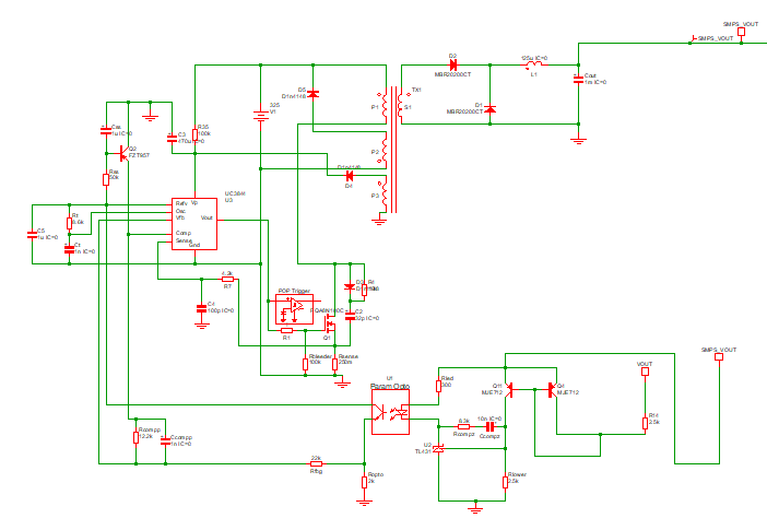
  3. This is my SMPS schematic:

enter image description here

I am designing a 30V 5A lab bench power supply having SMPS as a pre-regulator for the linear stage which will keep the SMPS output always 4V higher than the main output voltage. This means SMPS output will be varying from 4V to 34V. For SMPS, I have used forward topology and therefore it requires a minimum load to operate properly. After some trial and error in the simulation, I found out that it requires a 1.2W minimum load at its output and therefore I want to have some margin and want to place a 2W load at the output. But since the output voltage will be varying from 4V to 30V I can not just put a resistor at the output because if it is dissipating 2W at 4V then it will be dissipating 144.5W at 34V which is obviously not practical.

Is there any simple way that requires only a few components to overcome this problem?

EDIT: Extra details if required:

  1. I am using UC3844 as the controller IC. Link to datasheet.

  2. I have tried using opamp to maintain a constant voltage across a resistor and hence the power dissipated by it but the rest of the voltage is dropped across a BJT which is carrying the same current as of the resistor and therefore in total around 17W(BJT and resistor combined) is dissipated at 34V which is still pretty high.

  3. This is my SMPS schematic:

enter image description here

I am designing a 30 V 5 A lab bench power supply having SMPS as a pre-regulator for the linear stage which will keep the SMPS output always 4 V higher than the main output voltage. This means SMPS output will be varying from 4 V to 34 V. For SMPS, I have used forward topology and therefore it requires a minimum load to operate properly. After some trial and error in the simulation, I found out that it requires a 1.2 W minimum load at its output and therefore I want to have some margin and want to place a 2 W load at the output. But since the output voltage will be varying from 4 V to 30 V I can not just put a resistor at the output because if it is dissipating 2 W at 4 V then it will be dissipating 144.5 W at 34 V which is obviously not practical.

Is there any simple way that requires only a few components to overcome this problem?

EDIT: Extra details if required:

  1. I am using UC3844 as the controller IC. Link to datasheet.

  2. I have tried using opamp to maintain a constant voltage across a resistor and hence the power dissipated by it but the rest of the voltage is dropped across a BJT which is carrying the same current as of the resistor and therefore in total around 17 W (BJT and resistor combined) is dissipated at 34 V which is still pretty high.

  3. This is my SMPS schematic:

enter image description here

added 120 characters in body
Source Link
tinkerer
  • 180
  • 11

I am designing a 30V 5A lab bench power supply having SMPS as a pre-regulator for the linear stage which will keep the SMPS output always 4V higher than the main output voltage. This means SMPS output will be varying from 4V to 34V. For SMPS, I have used forward topology and therefore it requires a minimum load to operate properly. After some trial and error in the simulation, I found out that it requires a 1.2W minimum load at its output and therefore I want to have some margin and want to place a 2W load at the output. But since the output voltage will be varying from 4V to 30V I can not just put a resistor at the output because if it is dissipating 2W at 4V then it will be dissipating 144.5W at 34V which is obviously not practical.

Is there any simple way that requires only a few components to overcome this problem?

EDIT: Extra details if required:

  1. I am using UC3844 as the controller IC. Link to datasheet.

    I am using UC3844 as the controller IC. Link to datasheet.

  2. I have tried using opamp to maintain a constant voltage across a resistor and hence the power dissipated by it but the rest of the voltage is dropped across a BJT which is carrying the same current as of the resistor and therefore in total around 17W(BJT and resistor combined) is dissipated at 34V which is still pretty high.

    I have tried using opamp to maintain a constant voltage across a resistor and hence the power dissipated by it but the rest of the voltage is dropped across a BJT which is carrying the same current as of the resistor and therefore in total around 17W(BJT and resistor combined) is dissipated at 34V which is still pretty high.

  3. This is my SMPS schematic:

enter image description here

I am designing a 30V 5A lab bench power supply having SMPS as a pre-regulator for the linear stage which will keep the SMPS output always 4V higher than the main output voltage. This means SMPS output will be varying from 4V to 34V. For SMPS, I have used forward topology and therefore it requires a minimum load to operate properly. After some trial and error in the simulation, I found out that it requires a 1.2W minimum load at its output and therefore I want to have some margin and want to place a 2W load at the output. But since the output voltage will be varying from 4V to 30V I can not just put a resistor at the output because if it is dissipating 2W at 4V then it will be dissipating 144.5W at 34V which is obviously not practical.

Is there any simple way that requires only a few components to overcome this problem?

EDIT: Extra details if required:

  1. I am using UC3844 as the controller IC. Link to datasheet.
  2. I have tried using opamp to maintain a constant voltage across a resistor and hence the power dissipated by it but the rest of the voltage is dropped across a BJT which is carrying the same current as of the resistor and therefore in total around 17W(BJT and resistor combined) is dissipated at 34V which is still pretty high.

I am designing a 30V 5A lab bench power supply having SMPS as a pre-regulator for the linear stage which will keep the SMPS output always 4V higher than the main output voltage. This means SMPS output will be varying from 4V to 34V. For SMPS, I have used forward topology and therefore it requires a minimum load to operate properly. After some trial and error in the simulation, I found out that it requires a 1.2W minimum load at its output and therefore I want to have some margin and want to place a 2W load at the output. But since the output voltage will be varying from 4V to 30V I can not just put a resistor at the output because if it is dissipating 2W at 4V then it will be dissipating 144.5W at 34V which is obviously not practical.

Is there any simple way that requires only a few components to overcome this problem?

EDIT: Extra details if required:

  1. I am using UC3844 as the controller IC. Link to datasheet.

  2. I have tried using opamp to maintain a constant voltage across a resistor and hence the power dissipated by it but the rest of the voltage is dropped across a BJT which is carrying the same current as of the resistor and therefore in total around 17W(BJT and resistor combined) is dissipated at 34V which is still pretty high.

  3. This is my SMPS schematic:

enter image description here

added 477 characters in body
Source Link
tinkerer
  • 180
  • 11

I am designing a 30V 5A lab bench power supply having SMPS as a pre-regulator for the linear stage which will keep the SMPS output always 4V higher than the main output voltage. This means SMPS output will be varying from 4V to 34V. For SMPS, I have used forward topology and therefore it requires a minimum load to operate properly. After some trial and error in the simulation, I found out that it requires a 1.2W minimum load at its output and therefore I want to have some margin and want to place a 2W load at the output. But since the output voltage will be varying from 4V to 30V I can not just put a resistor at the output because if it is dissipating 2W at 4V then it will be dissipating 144.5W at 34V which is obviously not practical.

Is there any simple way that requires only a few components to overcome this problem?

EDIT: Extra details if required:

  1. I am using UC3844 as the controller IC. Link to datasheet.
  2. I have tried using opamp to maintain a constant voltage across a resistor and hence the power dissipated by it but the rest of the voltage is dropped across a BJT which is carrying the same current as of the resistor and therefore in total around 17W(BJT and resistor combined) is dissipated at 34V which is still pretty high.

I am designing a 30V 5A lab bench power supply having SMPS as a pre-regulator for the linear stage which will keep the SMPS output always 4V higher than the main output voltage. This means SMPS output will be varying from 4V to 34V. For SMPS, I have used forward topology and therefore it requires a minimum load to operate properly. After some trial and error in the simulation, I found out that it requires a 1.2W minimum load at its output and therefore I want to have some margin and want to place a 2W load at the output. But since the output voltage will be varying from 4V to 30V I can not just put a resistor at the output because if it is dissipating 2W at 4V then it will be dissipating 144.5W at 34V which is obviously not practical.

Is there any simple way that requires only a few components to overcome this problem?

EDIT: Extra details if required:

  1. I am using UC3844 as the controller IC. Link to datasheet.
  2. I have tried using opamp to maintain a constant voltage across a resistor and hence the power dissipated by it but the rest of the voltage is dropped across a BJT which is carrying the same current as of the resistor and therefore in total around 17W(BJT and resistor combined) is dissipated at 34V which is still pretty high.
Source Link
tinkerer
  • 180
  • 11
Loading