added 496 characters in body
Source Link
Andy aka
  • 473.1k
  • 29
  • 383
  • 839

The problem is I do not know which values of frequencies I should be testing, or at which frequency value I should know that the gain does not change.

This is where you test it and find out. OK, a pro would be able to estimate where these points in the spectrum are but, given that it's an experiment, you should try it at different frequencies and discover those points. The whole idea about an experiment (your words) is that it is a voyage of discovery.

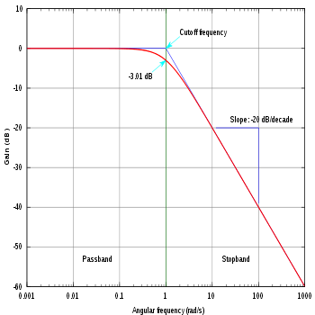
As for the dividing by \$\sqrt2\$, this relates to the half power points of the spectrum that you uncover in your experiment. Here's a simple magnitude bode plot of a single-order low pass-pass filter: -

enter image description here

Picture from here.

A signal that falls to 3 dB below its nominal maximum level level is said to have reduced in power by 2. Consider this; if the original signal was 10 volts at its nominal maximum level then, the power associated with that signal into a 1 Ω load would be: -

$$V^2/R = 100/1 = 100\text{ watts}$$

Half the power level would be 50 watts and that would be a voltage of: -

$$V = \sqrt{50\text{ watts}\times 1 \text{ ohm}} = 7.071 \text{ volts}$$

Or, put another way 10 volts divided by \$\sqrt2\$

And, in decibel terms that's 3 dB down on 10 volts because 20 log (7.071/10) = 3.01 dB. Yes, 3.01 dB is strictly speaking the half power point but, as engineers we refer to it as the 3 dB point.

A friend of mine told me something about choosing voltage values at which distortion does not occur at the output signal. Also would appreciate a comment about this.

You should use your oscilloscope to ensure that the op-amp output does not visibly distort when making measurements in your experiment. Distortion is not your friend here (unless you are a guitarist) and, it can skew the 3 dB points a little if you are not careful about managing things correctly.

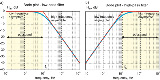
Here's another 2 bode plots (of a single-order low-pass and high-pass filter) with a little more information: -

enter image description here

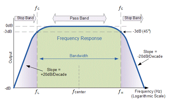
Image from here. The point of showing the above is that for many op-amp circuits, there can be two 3 dB points; one at a low frequency and one at a higher frequency. Think audio processing circuits for example. So, you might end up with an experiment that produces a magnitude bode plot like this: -

enter image description here

Image from here.

The problem is I do not know which values of frequencies I should be testing, or at which frequency value I should know that the gain does not change.

This is where you test it and find out. OK, a pro would be able to estimate where these points in the spectrum are but, given that it's an experiment, you should try it at different frequencies and discover those points. The whole idea about an experiment (your words) is that it is a voyage of discovery.

As for the dividing by \$\sqrt2\$, this relates to the half power points of the spectrum that you uncover in your experiment. Here's a simple magnitude bode plot of a low pass filter: -

enter image description here

Picture from here.

A signal that falls to 3 dB below its nominal maximum level level is said to have reduced in power by 2. Consider this; if the original signal was 10 volts at its nominal maximum level then, the power associated with that signal into a 1 Ω load would be: -

$$V^2/R = 100/1 = 100\text{ watts}$$

Half the power level would be 50 watts and that would be a voltage of: -

$$V = \sqrt{50\text{ watts}\times 1 \text{ ohm}} = 7.071 \text{ volts}$$

Or, put another way 10 volts divided by \$\sqrt2\$

And, in decibel terms that's 3 dB down on 10 volts because 20 log (7.071/10) = 3.01 dB. Yes, 3.01 dB is strictly speaking the half power point but, as engineers we refer to it as the 3 dB point.

A friend of mine told me something about choosing voltage values at which distortion does not occur at the output signal. Also would appreciate a comment about this.

You should use your oscilloscope to ensure that the op-amp output does not visibly distort when making measurements in your experiment. Distortion is not your friend here (unless you are a guitarist) and, it can skew the 3 dB points a little if you are not careful about managing things correctly.

The problem is I do not know which values of frequencies I should be testing, or at which frequency value I should know that the gain does not change.

This is where you test it and find out. OK, a pro would be able to estimate where these points in the spectrum are but, given that it's an experiment, you should try it at different frequencies and discover those points. The whole idea about an experiment (your words) is that it is a voyage of discovery.

As for the dividing by \$\sqrt2\$, this relates to the half power points of the spectrum that you uncover in your experiment. Here's a simple magnitude bode plot of a single-order low-pass filter: -

enter image description here

Picture from here.

A signal that falls to 3 dB below its nominal maximum level level is said to have reduced in power by 2. Consider this; if the original signal was 10 volts at its nominal maximum level then, the power associated with that signal into a 1 Ω load would be: -

$$V^2/R = 100/1 = 100\text{ watts}$$

Half the power level would be 50 watts and that would be a voltage of: -

$$V = \sqrt{50\text{ watts}\times 1 \text{ ohm}} = 7.071 \text{ volts}$$

Or, put another way 10 volts divided by \$\sqrt2\$

And, in decibel terms that's 3 dB down on 10 volts because 20 log (7.071/10) = 3.01 dB. Yes, 3.01 dB is strictly speaking the half power point but, as engineers we refer to it as the 3 dB point.

A friend of mine told me something about choosing voltage values at which distortion does not occur at the output signal. Also would appreciate a comment about this.

You should use your oscilloscope to ensure that the op-amp output does not visibly distort when making measurements in your experiment. Distortion is not your friend here (unless you are a guitarist) and, it can skew the 3 dB points a little if you are not careful about managing things correctly.

Here's another 2 bode plots (of a single-order low-pass and high-pass filter) with a little more information: -

enter image description here

Image from here. The point of showing the above is that for many op-amp circuits, there can be two 3 dB points; one at a low frequency and one at a higher frequency. Think audio processing circuits for example. So, you might end up with an experiment that produces a magnitude bode plot like this: -

enter image description here

Image from here.

Source Link
Andy aka
  • 473.1k
  • 29
  • 383
  • 839

The problem is I do not know which values of frequencies I should be testing, or at which frequency value I should know that the gain does not change.

This is where you test it and find out. OK, a pro would be able to estimate where these points in the spectrum are but, given that it's an experiment, you should try it at different frequencies and discover those points. The whole idea about an experiment (your words) is that it is a voyage of discovery.

As for the dividing by \$\sqrt2\$, this relates to the half power points of the spectrum that you uncover in your experiment. Here's a simple magnitude bode plot of a low pass filter: -

enter image description here

Picture from here.

A signal that falls to 3 dB below its nominal maximum level level is said to have reduced in power by 2. Consider this; if the original signal was 10 volts at its nominal maximum level then, the power associated with that signal into a 1 Ω load would be: -

$$V^2/R = 100/1 = 100\text{ watts}$$

Half the power level would be 50 watts and that would be a voltage of: -

$$V = \sqrt{50\text{ watts}\times 1 \text{ ohm}} = 7.071 \text{ volts}$$

Or, put another way 10 volts divided by \$\sqrt2\$

And, in decibel terms that's 3 dB down on 10 volts because 20 log (7.071/10) = 3.01 dB. Yes, 3.01 dB is strictly speaking the half power point but, as engineers we refer to it as the 3 dB point.

A friend of mine told me something about choosing voltage values at which distortion does not occur at the output signal. Also would appreciate a comment about this.

You should use your oscilloscope to ensure that the op-amp output does not visibly distort when making measurements in your experiment. Distortion is not your friend here (unless you are a guitarist) and, it can skew the 3 dB points a little if you are not careful about managing things correctly.