Tweeted twitter.com/StackElectronix/status/1491517282773831680
Became Hot Network Question
added 23 characters in body; edited tags; edited title
Source Link
ocrdu
  • 9.3k
  • 23
  • 32
  • 42

Is this a correct way to divide and 'clamp' a noisy 10V10 V signal to 3.3V3 V?

I need to read a noisy 10V hall10 V Hall sensor square wave signal using an STM32 (3.3V3 V logic). To

To reduce the voltage I can use a simple resistor voltage divider, however, I'm not certain how to protect the STM32 from voltage spikes in case the signal source goes over 10V10 V (or possibly below 0V0 V?).

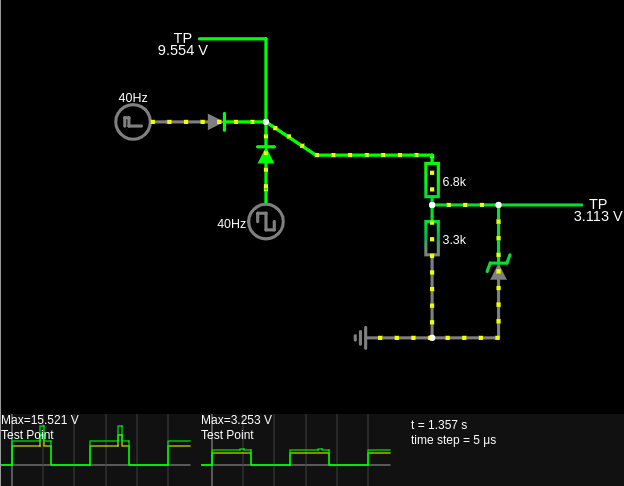
I put together this scheme using a 3.3V zener3 V Zener diode which seems to work in the simulation, but I'm concerned because other voltage protection circuits involve multiple zenerZener diodes  :  link

Also, I fail to understand why one would use zener diosedZener diodes over 'regular' diodes. Can't we just use a 'regular' diode from noisy 3.3V3 V to 3.3V3 V so that any excess voltage will flow to the 3.3V3 V voltage source, instead of zenera Zener diode from 0V0 V to noisy 3.3V3 V?   

enter image description here

Is this a correct way to divide and 'clamp' a noisy 10V signal to 3.3V?

I need to read a noisy 10V hall sensor square wave signal using an STM32 (3.3V logic). To reduce the voltage I can use a simple resistor voltage divider, however I'm not certain how to protect the STM32 from voltage spikes in case the signal source goes over 10V (or possibly below 0V?).

I put together this scheme using a 3.3V zener diode which seems to work in the simulation, but I'm concerned because other voltage protection circuits involve multiple zener diodes  :link

Also, I fail to understand why one would use zener diosed over 'regular' diodes. Can't we just use a 'regular' diode from noisy 3.3V to 3.3V so that any excess voltage will flow to the 3.3V voltage source, instead of zener from 0V to noisy 3.3V?  enter image description here

Is this a correct way to divide and 'clamp' a noisy 10 V signal to 3.3 V?

I need to read a noisy 10 V Hall sensor square wave signal using an STM32 (3.3 V logic).

To reduce the voltage I can use a simple resistor voltage divider, however, I'm not certain how to protect the STM32 from voltage spikes in case the signal source goes over 10 V (or possibly below 0 V?).

I put together this scheme using a 3.3 V Zener diode which seems to work in the simulation, but I'm concerned because other voltage protection circuits involve multiple Zener diodes:  link

Also, I fail to understand why one would use Zener diodes over 'regular' diodes. Can't we just use a 'regular' diode from noisy 3.3 V to 3.3 V so that any excess voltage will flow to the 3.3 V voltage source, instead of a Zener diode from 0 V to noisy 3.3 V? 

enter image description here

Source Link

Is this a correct way to divide and 'clamp' a noisy 10V signal to 3.3V?

I need to read a noisy 10V hall sensor square wave signal using an STM32 (3.3V logic). To reduce the voltage I can use a simple resistor voltage divider, however I'm not certain how to protect the STM32 from voltage spikes in case the signal source goes over 10V (or possibly below 0V?).

I put together this scheme using a 3.3V zener diode which seems to work in the simulation, but I'm concerned because other voltage protection circuits involve multiple zener diodes :link

Also, I fail to understand why one would use zener diosed over 'regular' diodes. Can't we just use a 'regular' diode from noisy 3.3V to 3.3V so that any excess voltage will flow to the 3.3V voltage source, instead of zener from 0V to noisy 3.3V? enter image description here