added 215 characters in body
Source Link
D.A.S.
  • 147.9k
  • 3
  • 56
  • 190

schematic

simulate this circuit – Schematic created using CircuitLab

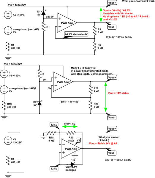
I think there are too many problems with your present config.

options:

  1. Battery charger design 14.2V + motorcycle battery, stable, most power
  2. LM317 with bypass
  3. DCDC regulator to 1V above a linear power regulator, More efficient, less heat rise.
  4. DCDC regulator to meet or exceed all above requirements. Most efficient, quiet like PC power supplies.

modified Option 2. enter image description here

Won't work
Input is too low and needs 20V with 1 ohm drop @ 6A for 14.2 out

Option 2 needs a rugged FET to handle linear failure modes using LM317 (search site for details)

Best bang for the buck

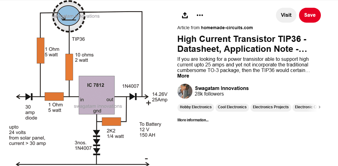
Option 1 using Option 2 with thermal protection (both FET and LM317 mounted to same heatsink. Car batteries have very low ESR thus can be regulated well at high step currents.

https://www.pinterest.ca/pin/618611698800362777

Future work

enter image description here https://www.analog.com/en/design-center/design-tools-and-calculators/power-management-tools.html LTPowerCAD

schematic

simulate this circuit – Schematic created using CircuitLab

I think there are too many problems with your present config.

options:

  1. Battery charger design 14.2V + motorcycle battery, stable, most power
  2. LM317 with bypass
  3. DCDC regulator to 1V above a linear power regulator, More efficient, less heat rise.
  4. DCDC regulator to meet or exceed all above requirements. Most efficient, quiet like PC power supplies.

modified Option 2. enter image description here

Won't work
Input is too low and needs 20V with 1 ohm drop @ 6A for 14.2 out

Option 2 needs a rugged FET to handle linear failure modes using LM317 (search site for details)

Best bang for the buck

Option 1 using Option 2 with thermal protection (both FET and LM317 mounted to same heatsink. Car batteries have very low ESR thus can be regulated well at high step currents.

https://www.pinterest.ca/pin/618611698800362777

Future work

enter image description here https://www.analog.com/en/design-center/design-tools-and-calculators/power-management-tools.html LTPowerCAD

added 206 characters in body
Source Link
D.A.S.
  • 147.9k
  • 3
  • 56
  • 190

schematic

simulate this circuit – Schematic created using CircuitLab

I think there are too many problems with your present config.

options:

  1. Battery charger design 14.2V + motorcycle battery, stable, most power
  2. LM317 with bypass
  3. DCDC regulator to 1V above a linear power regulator, More efficient, less heat rise.
  4. DCDC regulator to meet or exceed all above requirements. Most efficient, quiet like PC power supplies.

modified Option 2. enter image description here

Won't work
Input is too low and needs 20V with 1 ohm drop @ 6A for 14.2 out

Option 2 needs a rugged FET to handle linear failure modes using LM317 (search site for details)

Best bang for the buck

htps://wwwOption 1 using Option 2 with thermal protection (both FET and LM317 mounted to same heatsink.pinterest Car batteries have very low ESR thus can be regulated well at high step currents.ca/pin/618611698800362777

https://www.pinterest.ca/pin/618611698800362777

schematic

simulate this circuit – Schematic created using CircuitLab

I think there are too many problems with your present config.

options:

  1. Battery charger design 14.2V + motorcycle battery, stable, most power
  2. LM317 with bypass
  3. DCDC regulator to 1V above a linear power regulator, More efficient, less heat rise.
  4. DCDC regulator to meet or exceed all above requirements. Most efficient, quiet like PC power supplies.

modified Option 2. enter image description here

Won't work
Input is too low and needs 20V with 1 ohm drop @ 6A for 14.2 out

Option 2 needs a rugged FET to handle linear failure modes using LM317 (search site for details)

htps://www.pinterest.ca/pin/618611698800362777

schematic

simulate this circuit – Schematic created using CircuitLab

I think there are too many problems with your present config.

options:

  1. Battery charger design 14.2V + motorcycle battery, stable, most power
  2. LM317 with bypass
  3. DCDC regulator to 1V above a linear power regulator, More efficient, less heat rise.
  4. DCDC regulator to meet or exceed all above requirements. Most efficient, quiet like PC power supplies.

modified Option 2. enter image description here

Won't work
Input is too low and needs 20V with 1 ohm drop @ 6A for 14.2 out

Option 2 needs a rugged FET to handle linear failure modes using LM317 (search site for details)

Best bang for the buck

Option 1 using Option 2 with thermal protection (both FET and LM317 mounted to same heatsink. Car batteries have very low ESR thus can be regulated well at high step currents.

https://www.pinterest.ca/pin/618611698800362777

added 261 characters in body
Source Link
D.A.S.
  • 147.9k
  • 3
  • 56
  • 190

schematicschematic

simulate this circuitsimulate this circuit – Schematic created using CircuitLab

I think there are too many problems with your present config.

options:

  1. Battery charger design 14.2V + motorcycle battery, stable, most power
  2. LM317 with bypass
  3. DCDC regulator to 1V above a linear power regulator, More efficient, less heat rise.
  4. DCDC regulator to meet or exceed all above requirements. Most efficient, quiet like PC power supplies.

modified Option 2. enter image description here

https://www.pinterest.ca/pin/618611698800362777Won't work
Input is too low and needs 20V with 1 ohm drop @ 6A for 14.2 out

Option 2 needs a rugged FET to handle linear failure modes using LM317 (search site for details)

htps://www.pinterest.ca/pin/618611698800362777

schematic

simulate this circuit – Schematic created using CircuitLab

I think there are too many problems with your present config.

options:

  1. Battery charger design 14.2V + motorcycle battery, stable, most power
  2. LM317 with bypass
  3. DCDC regulator to 1V above a linear power regulator, More efficient, less heat rise.
  4. DCDC regulator to meet or exceed all above requirements. Most efficient, quiet like PC power supplies.

Option 2. enter image description here

https://www.pinterest.ca/pin/618611698800362777

schematic

simulate this circuit – Schematic created using CircuitLab

I think there are too many problems with your present config.

options:

  1. Battery charger design 14.2V + motorcycle battery, stable, most power
  2. LM317 with bypass
  3. DCDC regulator to 1V above a linear power regulator, More efficient, less heat rise.
  4. DCDC regulator to meet or exceed all above requirements. Most efficient, quiet like PC power supplies.

modified Option 2. enter image description here

Won't work
Input is too low and needs 20V with 1 ohm drop @ 6A for 14.2 out

Option 2 needs a rugged FET to handle linear failure modes using LM317 (search site for details)

htps://www.pinterest.ca/pin/618611698800362777

added 261 characters in body
Source Link
D.A.S.
  • 147.9k
  • 3
  • 56
  • 190
Loading
Source Link
D.A.S.
  • 147.9k
  • 3
  • 56
  • 190
Loading