Rollback to Revision 2
Source Link

Design of a filteran A frequency weighting circuit

I gotstarted by doing what is described in the image below.

enter image description here

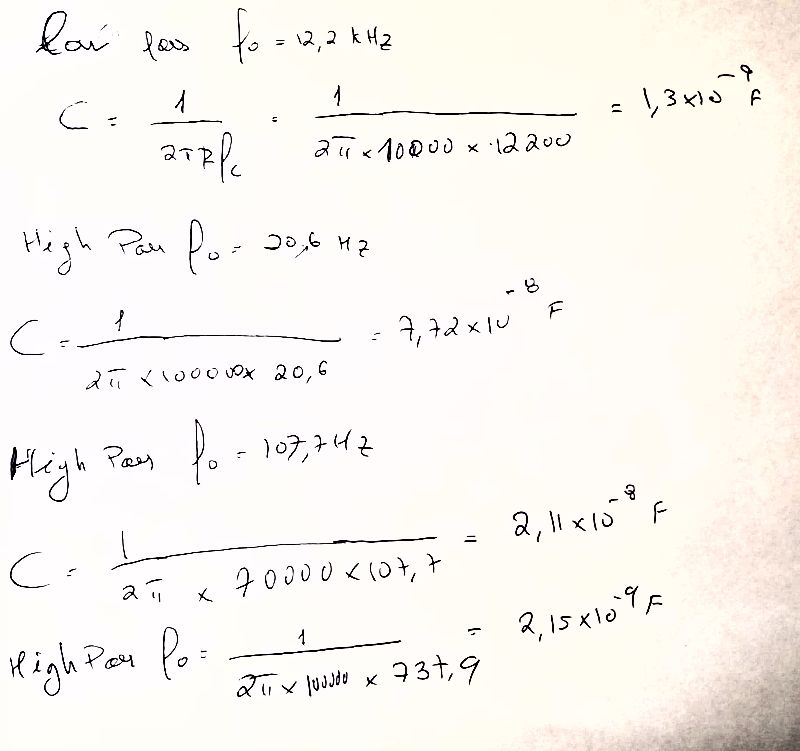
Some simple calculations were made and I obtained these capacitance values:

enter image description here

The values I placed for the resistors were at random.

Then implemented this response in LTspice:

enter image description here

Igot this response:

enter image description here

The ideal response should look like this:

enter image description here

For example, at 1000Hz it is -15dB when it should be 0dB.

Do you guys have any idea how to fix this?

I also have no idea how can we go from the transfer function to the circuit shown in the first picture I placed here. In the document I found (that has figure 2.5) there's no mention about that, and I can't seem to find anything about it in other places.

Design of a filter circuit

I got this response in LTspice:

enter image description here

The ideal response should look like this:

enter image description here

For example, at 1000Hz it is -15dB when it should be 0dB.

Do you guys have any idea how to fix this?

I also have no idea how can we go from the transfer function to the circuit shown in the first picture I placed here. In the document I found (that has figure 2.5) there's no mention about that, and I can't seem to find anything about it in other places.
Design of an A frequency weighting circuit

I started by doing what is described in the image below.

enter image description here

Some simple calculations were made and I obtained these capacitance values:

enter image description here

The values I placed for the resistors were at random.

Then implemented this in LTspice:

enter image description here

Igot this response:

enter image description here

The ideal response should look like this:

enter image description here

For example, at 1000Hz it is -15dB when it should be 0dB.

Do you guys have any idea how to fix this?

I also have no idea how can we go from the transfer function to the circuit shown in the first picture I placed here. In the document I found (that has figure 2.5) there's no mention about that, and I can't seem to find anything about it in other places.

edited title
Link
Scipio
  • 803
  • 5
  • 9

Design of an A frequency weightinga filter circuit

deleted 361 characters in body
Source Link
Scipio
  • 803
  • 5
  • 9

I started by doing what is described in the image below.

enter image description here

Some simple calculations were made and I obtained these capacitance values:

enter image description here

The values I placed for the resistors were at random.

Then implementedgot this response in LTspice:

enter image description here

Igot this response:

enter image description here

The ideal response should look like this:

enter image description here

For example, at 1000Hz it is -15dB when it should be 0dB.

Do you guys have any idea how to fix this?

I also have no idea how can we go from the transfer function to the circuit shown in the first picture I placed here. In the document I found (that has figure 2.5) there's no mention about that, and I can't seem to find anything about it in other places.

I started by doing what is described in the image below.

enter image description here

Some simple calculations were made and I obtained these capacitance values:

enter image description here

The values I placed for the resistors were at random.

Then implemented this in LTspice:

enter image description here

Igot this response:

enter image description here

The ideal response should look like this:

enter image description here

For example, at 1000Hz it is -15dB when it should be 0dB.

Do you guys have any idea how to fix this?

I also have no idea how can we go from the transfer function to the circuit shown in the first picture I placed here. In the document I found (that has figure 2.5) there's no mention about that, and I can't seem to find anything about it in other places.
I got this response in LTspice:

enter image description here

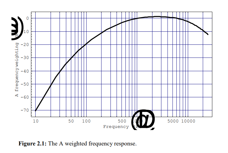
The ideal response should look like this:

enter image description here

For example, at 1000Hz it is -15dB when it should be 0dB.

Do you guys have any idea how to fix this?

I also have no idea how can we go from the transfer function to the circuit shown in the first picture I placed here. In the document I found (that has figure 2.5) there's no mention about that, and I can't seem to find anything about it in other places.

Tweeted twitter.com/StackElectronix/status/1549046340700610561
Became Hot Network Question
deleted 7 characters in body; edited title
Source Link
JRE
  • 73.6k
  • 10
  • 112
  • 195
Loading
Source Link
Scipio
  • 803
  • 5
  • 9
Loading