added 131 characters in body
Source Link
Andy aka
  • 472.9k
  • 29
  • 382
  • 839

The web page you linked also has a data sheet link but, the data sheet isn't particularly helpful at figuring out the load capacitance. At that point (and seeing contradictions between the seller's web-page and poor documentation in the data sheet) I would look elsewhere for a crystal.

However, if you trust the web page it specifies a load capacitance of 9 pF and that usually means 18 pF on one crystal pin to ground and 18 pF on the other crystal pin to ground. Clearly you should take into account the stray capacitance but, you would need to know what the input port's capacitance is; this will be the dominant modifier and it might be in the realm of 2 to 5 pF. I'm not going to guess.

If I'm off by for example 5pF, how much of an impact does that have on the crystal? Is it a very small error like 0.01Mhz or can it go several Mhz off?

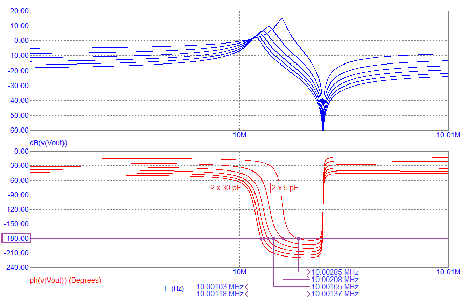
It won't drastically affect the operating frequency. For instance, this picture (from my very basic web site) shows a typical 10 MHz (series resonance) crystal and how much oscillation frequency might shift with quite drastic changes in loading capacitance: -

enter image description here

For a load capacitance change of 2 × 5 pF to 2 × 30 pF, the oscillation frequency moves about 2 kHz or 200 parts per million.

  • For a load capacitance change of 2 × 5 pF to 2 × 30 pF, the oscillation frequency moves about 2 kHz or 182 parts per million.

  • This is excessive compared to maybe having a crystal optimized for 2 × 10 pF and fitting 2 × 15 pF (43 ppm).

The web page you linked also has a data sheet link but, the data sheet isn't particularly helpful at figuring out the load capacitance. At that point (and seeing contradictions between the seller's web-page and poor documentation in the data sheet) I would look elsewhere for a crystal.

However, if you trust the web page it specifies a load capacitance of 9 pF and that usually means 18 pF on one crystal pin to ground and 18 pF on the other crystal pin to ground. Clearly you should take into account the stray capacitance but, you would need to know what the input port's capacitance is; this will be the dominant modifier and it might be in the realm of 2 to 5 pF. I'm not going to guess.

If I'm off by for example 5pF, how much of an impact does that have on the crystal? Is it a very small error like 0.01Mhz or can it go several Mhz off?

It won't drastically affect the operating frequency. For instance, this picture (from my very basic web site) shows a typical 10 MHz (series resonance) crystal and how much oscillation frequency might shift with quite drastic changes in loading capacitance: -

enter image description here

For a load capacitance change of 2 × 5 pF to 2 × 30 pF, the oscillation frequency moves about 2 kHz or 200 parts per million.

The web page you linked also has a data sheet link but, the data sheet isn't particularly helpful at figuring out the load capacitance. At that point (and seeing contradictions between the seller's web-page and poor documentation in the data sheet) I would look elsewhere for a crystal.

However, if you trust the web page it specifies a load capacitance of 9 pF and that usually means 18 pF on one crystal pin to ground and 18 pF on the other crystal pin to ground. Clearly you should take into account the stray capacitance but, you would need to know what the input port's capacitance is; this will be the dominant modifier and it might be in the realm of 2 to 5 pF. I'm not going to guess.

If I'm off by for example 5pF, how much of an impact does that have on the crystal? Is it a very small error like 0.01Mhz or can it go several Mhz off?

It won't drastically affect the operating frequency. For instance, this picture (from my very basic web site) shows a typical 10 MHz (series resonance) crystal and how much oscillation frequency might shift with quite drastic changes in loading capacitance: -

enter image description here

  • For a load capacitance change of 2 × 5 pF to 2 × 30 pF, the oscillation frequency moves about 2 kHz or 182 parts per million.

  • This is excessive compared to maybe having a crystal optimized for 2 × 10 pF and fitting 2 × 15 pF (43 ppm).

Source Link
Andy aka
  • 472.9k
  • 29
  • 382
  • 839

The web page you linked also has a data sheet link but, the data sheet isn't particularly helpful at figuring out the load capacitance. At that point (and seeing contradictions between the seller's web-page and poor documentation in the data sheet) I would look elsewhere for a crystal.

However, if you trust the web page it specifies a load capacitance of 9 pF and that usually means 18 pF on one crystal pin to ground and 18 pF on the other crystal pin to ground. Clearly you should take into account the stray capacitance but, you would need to know what the input port's capacitance is; this will be the dominant modifier and it might be in the realm of 2 to 5 pF. I'm not going to guess.

If I'm off by for example 5pF, how much of an impact does that have on the crystal? Is it a very small error like 0.01Mhz or can it go several Mhz off?

It won't drastically affect the operating frequency. For instance, this picture (from my very basic web site) shows a typical 10 MHz (series resonance) crystal and how much oscillation frequency might shift with quite drastic changes in loading capacitance: -

enter image description here

For a load capacitance change of 2 × 5 pF to 2 × 30 pF, the oscillation frequency moves about 2 kHz or 200 parts per million.