added 4 characters in body
Source Link

Updated Again: 

I have been working on this project for a few weeks now, with an end goal of having a control panel to power our two 120 V induction motors and 6 lights on the control panel using two 120 V outlets. The motors can take a maximum current of 8.8 A so I am attempting to use some current from one of the outlets to power a 12 V converter. This part of the circuit uses a flyback in conjunction with a bridge rectifier, capacitors, and a LM317 voltage regulator to get a 12 VDC output. This is needed for the LEDs I am using (which have a voltage rating of 12 V) and for the coils of the relays that I've chosen to use to activate the motors.

The only thing I'm wondering/concerned about with this part is its longevity. Will it have any trouble running for hours at a time? And if so, what actions should I take to rectify this?

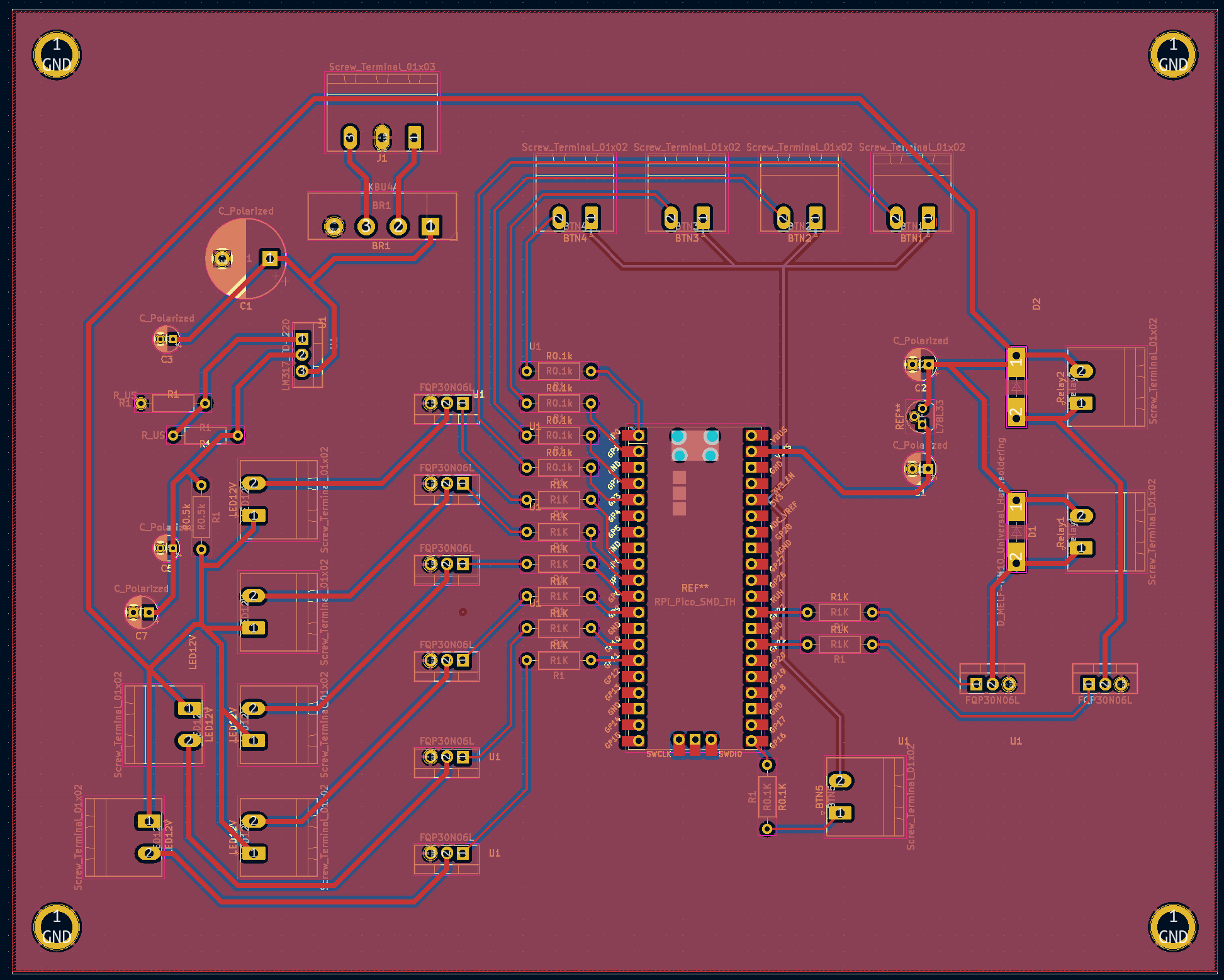
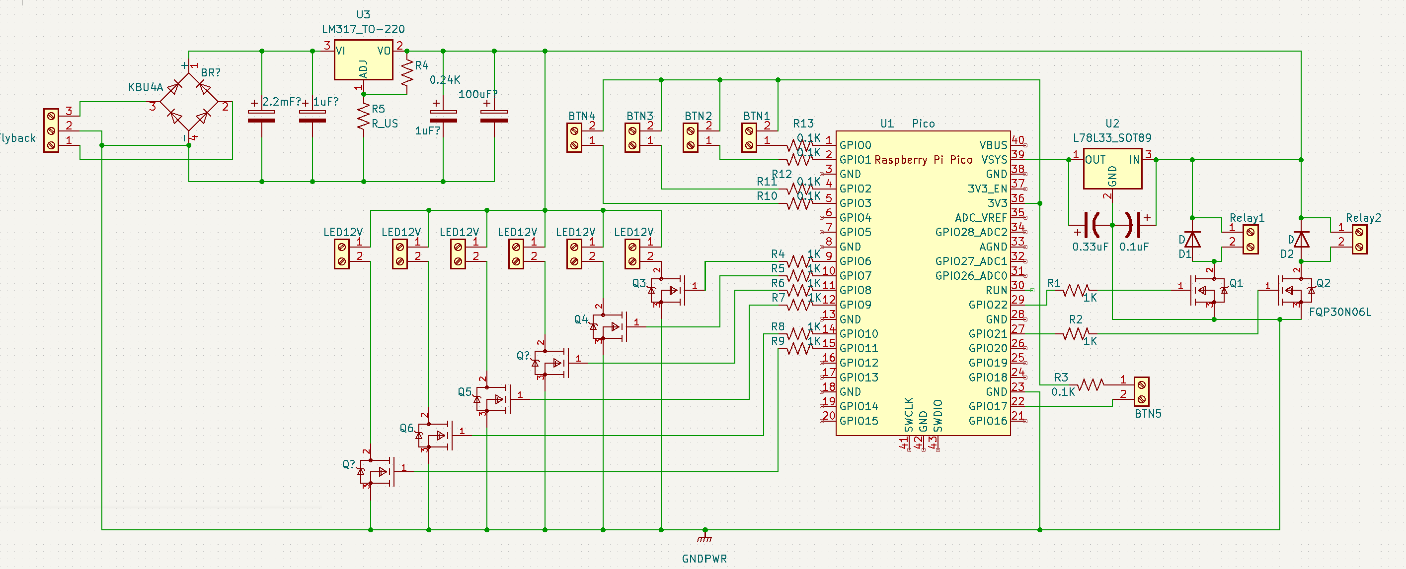
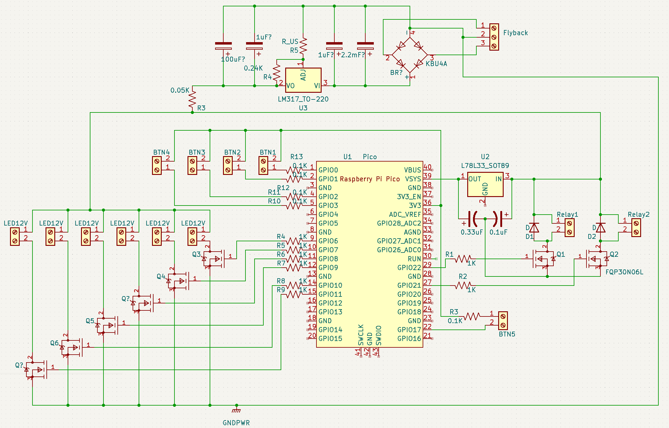
I redid the diagram in a more readable and understandable way, and have remade the PCB board with a ground plate on both sides connected to all of the 12V ground, and the ground from the base of the flyback. I also routed a ground from the pico to theground plane, and reoriented the power supply. Is this correct? Below is the full schematic without screw terminals:

Schematic Without Screw Terminals

Schematic With Screw Instead of external components

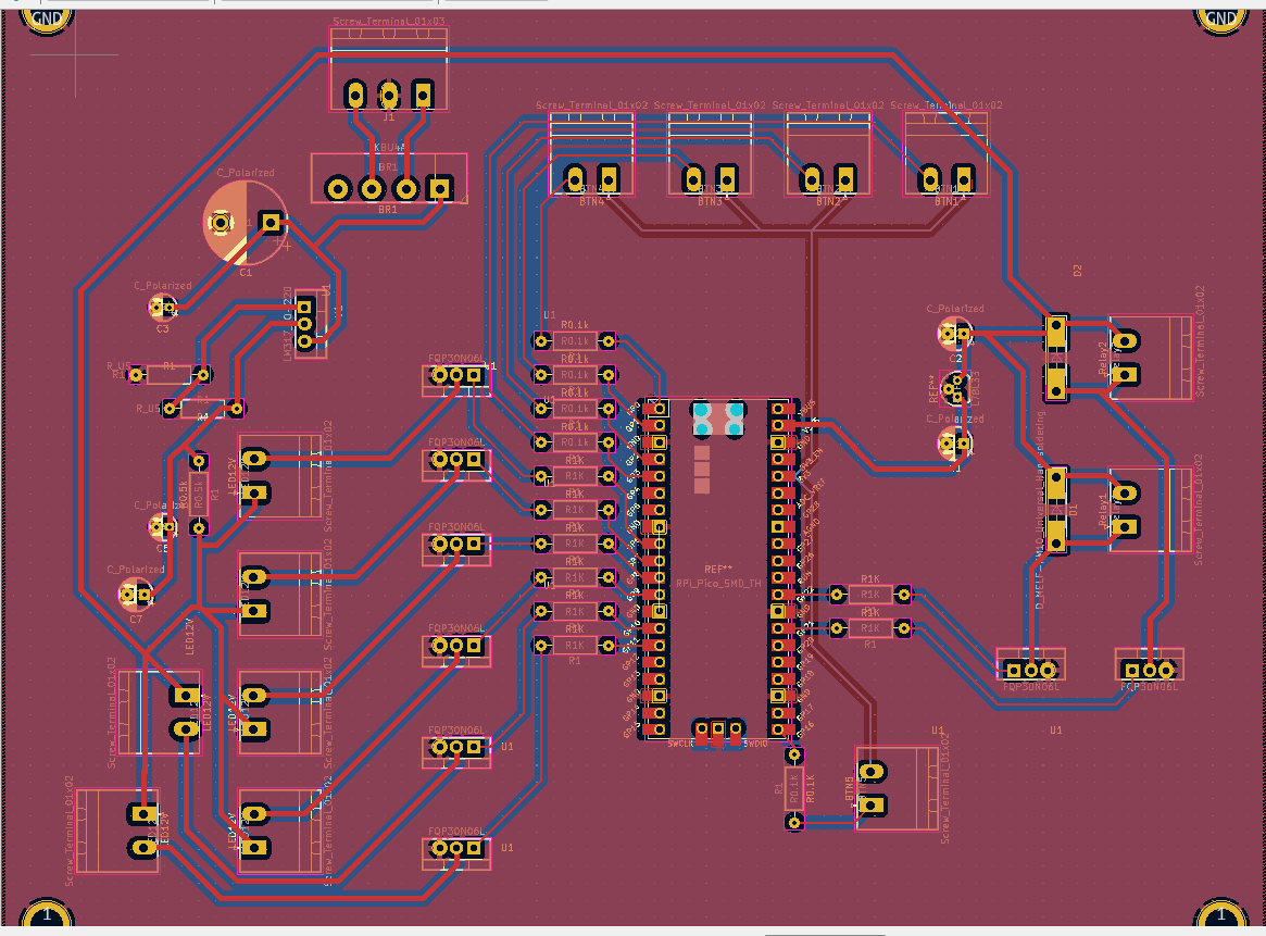
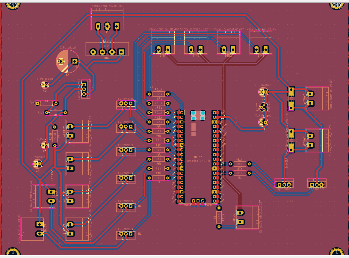
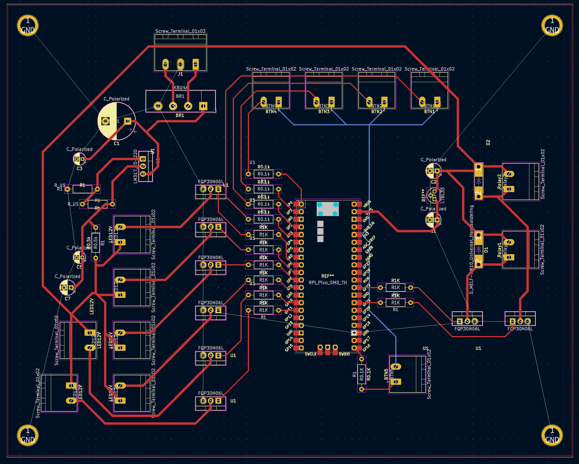
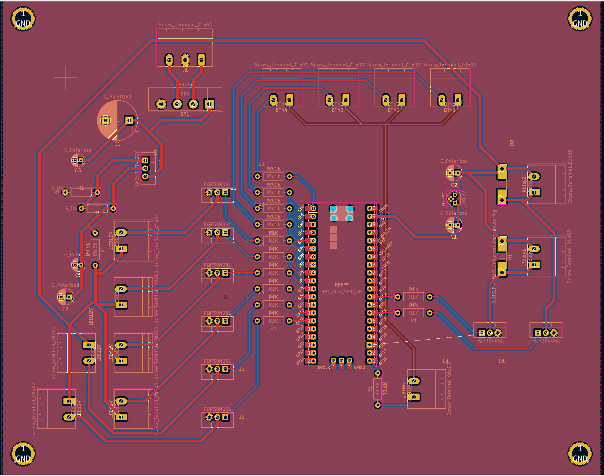
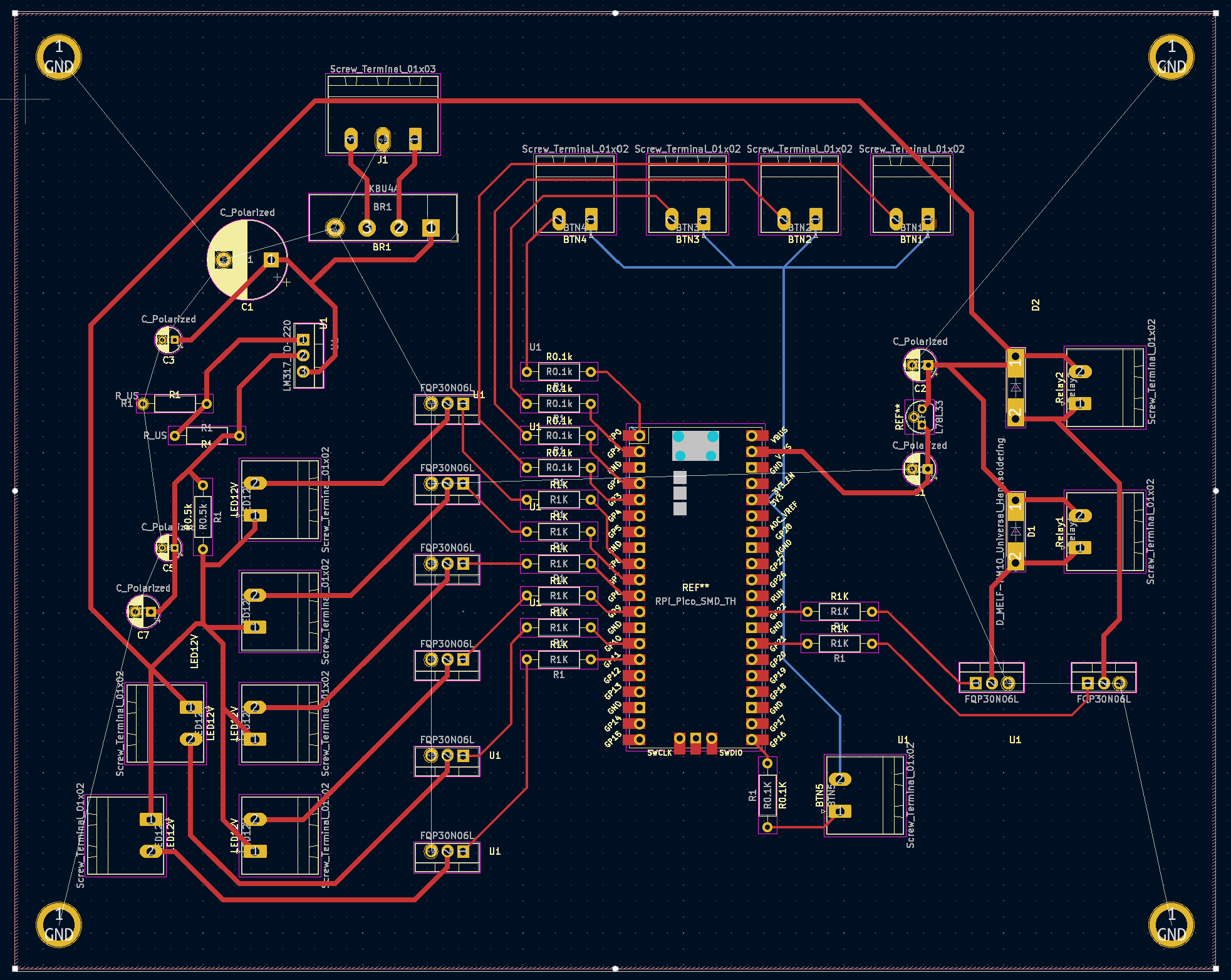
For the PCB boards, I believe I have done them correctly. I think I may need to space the FQP30N06L Mosfets apart more in order to fit the heat sinks, but other than that I think it should work. Would I need to do anything with the ground pin of the second 120V outlet, since im already connected to ground in a way? Should I add another screw terminal set and connect both grounds directly, or would that create a ground loop?

The PCB Without the Ground Plates

Full PCB

I also had a few additional questions. If these push buttons that I am using are rated for 660 V and 10 A would they even work with 3.3 V? At this point im considering using smaller ones. Lastly, is my spacing in between the ground and 12V traces going to be an issue if its too small, and if so how would I go about calculating that?

Updated Again: I have been working on this project for a few weeks now, with an end goal of having a control panel to power our two 120 V induction motors and 6 lights on the control panel using two 120 V outlets. The motors can take a maximum current of 8.8 A so I am attempting to use some current from one of the outlets to power a 12 V converter. This part of the circuit uses a flyback in conjunction with a bridge rectifier, capacitors, and a LM317 voltage regulator to get a 12 VDC output. This is needed for the LEDs I am using (which have a voltage rating of 12 V) and for the coils of the relays that I've chosen to use to activate the motors.

The only thing I'm wondering/concerned about with this part is its longevity. Will it have any trouble running for hours at a time? And if so, what actions should I take to rectify this?

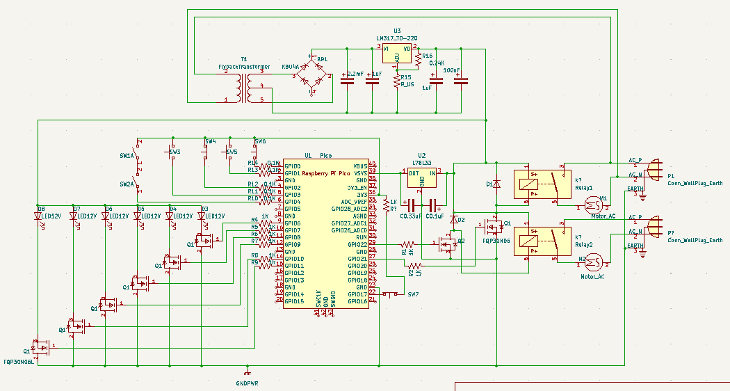
I redid the diagram in a more readable and understandable way, and have remade the PCB board with a ground plate on both sides connected to all of the 12V ground, and the ground from the base of the flyback. I also routed a ground from the pico to theground plane, and reoriented the power supply. Is this correct? Below is the full schematic without screw terminals:

Schematic Without Screw Terminals

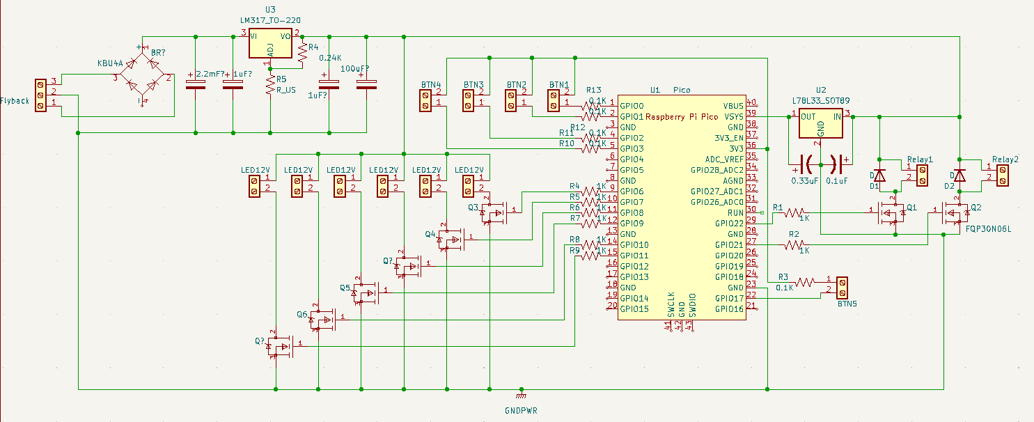
Schematic With Screw Instead of external components

For the PCB boards, I believe I have done them correctly. I think I may need to space the FQP30N06L Mosfets apart more in order to fit the heat sinks, but other than that I think it should work. Would I need to do anything with the ground pin of the second 120V outlet, since im already connected to ground in a way? Should I add another screw terminal set and connect both grounds directly, or would that create a ground loop?

The PCB Without the Ground Plates

Full PCB

I also had a few additional questions. If these push buttons that I am using are rated for 660 V and 10 A would they even work with 3.3 V? At this point im considering using smaller ones. Lastly, is my spacing in between the ground and 12V traces going to be an issue if its too small, and if so how would I go about calculating that?
Updated Again: 

I have been working on this project for a few weeks now, with an end goal of having a control panel to power our two 120 V induction motors and 6 lights on the control panel using two 120 V outlets. The motors can take a maximum current of 8.8 A so I am attempting to use some current from one of the outlets to power a 12 V converter. This part of the circuit uses a flyback in conjunction with a bridge rectifier, capacitors, and a LM317 voltage regulator to get a 12 VDC output. This is needed for the LEDs I am using (which have a voltage rating of 12 V) and for the coils of the relays that I've chosen to use to activate the motors.

The only thing I'm wondering/concerned about with this part is its longevity. Will it have any trouble running for hours at a time? And if so, what actions should I take to rectify this?

I redid the diagram in a more readable and understandable way, and have remade the PCB board with a ground plate on both sides connected to all of the 12V ground, and the ground from the base of the flyback. I also routed a ground from the pico to theground plane, and reoriented the power supply. Is this correct? Below is the full schematic without screw terminals:

Schematic Without Screw Terminals

Schematic With Screw Instead of external components

For the PCB boards, I believe I have done them correctly. I think I may need to space the FQP30N06L Mosfets apart more in order to fit the heat sinks, but other than that I think it should work. Would I need to do anything with the ground pin of the second 120V outlet, since im already connected to ground in a way? Should I add another screw terminal set and connect both grounds directly, or would that create a ground loop?

The PCB Without the Ground Plates

Full PCB

I also had a few additional questions. If these push buttons that I am using are rated for 660 V and 10 A would they even work with 3.3 V? At this point im considering using smaller ones. Lastly, is my spacing in between the ground and 12V traces going to be an issue if its too small, and if so how would I go about calculating that?
deleted 118 characters in body
Source Link

Updated Again: I have been working on this project for a few weeks now, with an end goal of having a control panel to power our two 120 V induction motors.

To preface, I know this is a stupid and convoluted way to go about this. There is no good or rational reason to use a microcontroller and programming in this circuit; however, this is for an extracurricular university project and we were told we would "get extra points if we include programming." So trust me, I already know how easy this would be without a MC, but it is stipulated in the rules.

The basic circuit I'm going for is a way to control two induction motors and 6 lights on the control panel withusing two 120 V outlets. The motors can take a max.maximum current of 8.8 A so I am attempting to use some current from one of the outlets to power a circuit that I already have milled12 V converter. This secondarypart of the circuit uses a flyback in conjunction with a bridge rectifier, capacitors, and somea LM317 voltage regulator chips to get a 12 VDC output. This is needed for the LEDs I am using (which have a voltage rating of 12 V) and for the coils of the relays that I've chosen to use to activate the motors.

The only thing I'm wondering/concerned about with this part is its longevity. Will it have any trouble running for hours at a time? And if so, what actions should I take to rectify this?

UPDATE:

Thank you for all the feedback, It was extremely helpful! I redid the diagram in a more readable and understandable way, and have remade the PCB board with a ground plate on both sides connected to all of the 12V ground, and the ground from the base of the flyback. I also routed a ground from the pico to theground plane, and reoriented the power supply. Is this correct? Below is the full schematic without screw terminals:

Schematics and PCB Schematic with Screw Terminals PCB Without Ground Plane PCBSchematic Without Screw Terminals

Schematic With Screw Instead of external components

For the PCB boards, I believe I have done them correctly. I think I may need to space the FQP30N06L Mosfets apart more in order to fit the heat sinks, but other than that I think it should work. Would I need to do anything with the ground pin of the second 120V outlet, since im already connected to ground in a way? Should I add another screw terminal set and connect both grounds directly, or would that create a ground loop?

The PCB Without the Ground Plates

Full PCB

I also had a few additional questions. If these push buttons that I am using are rated for 660 V and 10 A would they even work with 3.3 V? Also, sinceAt this point im considering using two outlets, should I rout the ground pin on both of them to the base plate? Or is it ok as it is, since its already connected to the one plug's ground?smaller ones. Lastly, is my spacing in between the ground and 12V traces going to be an issue if its too small, and if so how would I go about calculating that?
I have been working on this project for a few weeks now, with an end goal of having a control panel to power our two 120 V induction motors.

To preface, I know this is a stupid and convoluted way to go about this. There is no good or rational reason to use a microcontroller and programming in this circuit; however, this is for an extracurricular university project and we were told we would "get extra points if we include programming." So trust me, I already know how easy this would be without a MC, but it is stipulated in the rules.

The basic circuit I'm going for is a way to control two induction motors and 6 lights on the control panel with two 120 V outlets. The motors can take a max. current of 8.8 A so I am attempting to use some current from one of the outlets to power a circuit that I already have milled. This secondary circuit uses a flyback in conjunction with a bridge rectifier, capacitors, and some voltage regulator chips to get 12 VDC. This is needed for the LEDs I am using (which have a voltage rating of 12 V) and for the coils of the relays that I've chosen to use to activate the motors.

The only thing I'm wondering/concerned about with this part is its longevity. Will it have any trouble running for hours at a time? And if so, what actions should I take to rectify this?

UPDATE:

Thank you for all the feedback, It was extremely helpful! I redid the diagram in a more readable and understandable way, and have remade the PCB board with a ground plate on both sides connected to all of the 12V ground, and the ground from the base of the flyback. I also routed a ground from the pico to theground plane, and reoriented the power supply. Is this correct?

Schematics and PCB Schematic with Screw Terminals PCB Without Ground Plane PCB

I also had a few additional questions. If these push buttons that I am using are rated for 660 V and 10 A would they even work with 3.3 V? Also, since im using two outlets, should I rout the ground pin on both of them to the base plate? Or is it ok as it is, since its already connected to the one plug's ground? Lastly, is my spacing in between the ground and 12V traces going to be an issue if its too small, and if so how would I go about calculating that?
Updated Again: I have been working on this project for a few weeks now, with an end goal of having a control panel to power our two 120 V induction motors and 6 lights on the control panel using two 120 V outlets. The motors can take a maximum current of 8.8 A so I am attempting to use some current from one of the outlets to power a 12 V converter. This part of the circuit uses a flyback in conjunction with a bridge rectifier, capacitors, and a LM317 voltage regulator to get a 12 VDC output. This is needed for the LEDs I am using (which have a voltage rating of 12 V) and for the coils of the relays that I've chosen to use to activate the motors.

The only thing I'm wondering/concerned about with this part is its longevity. Will it have any trouble running for hours at a time? And if so, what actions should I take to rectify this?

I redid the diagram in a more readable and understandable way, and have remade the PCB board with a ground plate on both sides connected to all of the 12V ground, and the ground from the base of the flyback. I also routed a ground from the pico to theground plane, and reoriented the power supply. Is this correct? Below is the full schematic without screw terminals:

Schematic Without Screw Terminals

Schematic With Screw Instead of external components

For the PCB boards, I believe I have done them correctly. I think I may need to space the FQP30N06L Mosfets apart more in order to fit the heat sinks, but other than that I think it should work. Would I need to do anything with the ground pin of the second 120V outlet, since im already connected to ground in a way? Should I add another screw terminal set and connect both grounds directly, or would that create a ground loop?

The PCB Without the Ground Plates

Full PCB

I also had a few additional questions. If these push buttons that I am using are rated for 660 V and 10 A would they even work with 3.3 V? At this point im considering using smaller ones. Lastly, is my spacing in between the ground and 12V traces going to be an issue if its too small, and if so how would I go about calculating that?
added 73 characters in body
Source Link

I have been working on this project for a few weeks now, with an end goal of having a control panel to power our two 120 V induction motors.

To preface, I know this is a stupid and convoluted way to go about this. There is no good or rational reason to use a microcontroller and programming in this circuit; however, this is for an extracurricular university project and we were told we would "get extra points if we include programming." So trust me, I already know how easy this would be without a MC, but it is stipulated in the rules.

The basic circuit I'm going for is a way to control two induction motors and 6 lights on the control panel with two 120 V outlets. The motors can take a max. current of 8.8 A so I am attempting to use some current from one of the outlets to power a circuit that I already have milled. This secondary circuit uses a flyback in conjunction with a bridge rectifier, capacitors, and some voltage regulator chips to get 12 VDC. This is needed for the LEDs I am using (which have a voltage rating of 12 V) and for the coils of the relays that I've chosen to use to activate the motors.

The only thing I'm wondering/concerned about with this part is its longevity. Will it have any trouble running for hours at a time? And if so, what actions should I take to rectify this?

UPDATE:

Thank you for all the feedback, It was extremely helpful! I redid the diagram in a more readable and understandable way, and have remade the PCB board with a ground plate on both sides connected to all of the 12V ground, and the ground from the base of the flyback. I also routed a ground from the pico to theground plane, and reoriented the power supply. Is this correct? and how to I ensure there is no issues with ground loops?

enter image description hereSchematics and PCB enter image description hereSchematic with Screw Terminals enter image description herePCB Without Ground Plane PCB

I also had a few additional questions. If these push buttons that I am using are rated for 660 V and 10 A would they even work with 3.3 V? Also, since im using two outlets, should I rout the ground pin on both of them to the base plate? Or is it ok as it is, since its already connected to the one plug's ground? Lastly, is my spacing in between the ground and 12V traces going to be an issue if its too small, and if so how would I go about calculating that?
I have been working on this project for a few weeks now, with an end goal of having a control panel to power our two 120 V induction motors.

To preface, I know this is a stupid and convoluted way to go about this. There is no good or rational reason to use a microcontroller and programming in this circuit; however, this is for an extracurricular university project and we were told we would "get extra points if we include programming." So trust me, I already know how easy this would be without a MC, but it is stipulated in the rules.

The basic circuit I'm going for is a way to control two induction motors and 6 lights on the control panel with two 120 V outlets. The motors can take a max. current of 8.8 A so I am attempting to use some current from one of the outlets to power a circuit that I already have milled. This secondary circuit uses a flyback in conjunction with a bridge rectifier, capacitors, and some voltage regulator chips to get 12 VDC. This is needed for the LEDs I am using (which have a voltage rating of 12 V) and for the coils of the relays that I've chosen to use to activate the motors.

The only thing I'm wondering/concerned about with this part is its longevity. Will it have any trouble running for hours at a time? And if so, what actions should I take to rectify this?

UPDATE:

Thank you for all the feedback, It was extremely helpful! I redid the diagram in a more readable and understandable way, and have remade the PCB board with a ground plate on both sides connected to all of the 12V ground, and the ground from the base of the flyback. Is this correct? and how to I ensure there is no issues with ground loops?

enter image description here enter image description here enter image description here

I also had a few additional questions. If these push buttons that I am using are rated for 660 V and 10 A would they even work with 3.3 V? Also, since im using two outlets, should I rout the ground pin on both of them to the base plate? Or is it ok as it is, since its already connected to the one plug's ground? Lastly, is my spacing in between the ground and 12V traces going to be an issue if its too small, and if so how would I go about calculating that?
I have been working on this project for a few weeks now, with an end goal of having a control panel to power our two 120 V induction motors.

To preface, I know this is a stupid and convoluted way to go about this. There is no good or rational reason to use a microcontroller and programming in this circuit; however, this is for an extracurricular university project and we were told we would "get extra points if we include programming." So trust me, I already know how easy this would be without a MC, but it is stipulated in the rules.

The basic circuit I'm going for is a way to control two induction motors and 6 lights on the control panel with two 120 V outlets. The motors can take a max. current of 8.8 A so I am attempting to use some current from one of the outlets to power a circuit that I already have milled. This secondary circuit uses a flyback in conjunction with a bridge rectifier, capacitors, and some voltage regulator chips to get 12 VDC. This is needed for the LEDs I am using (which have a voltage rating of 12 V) and for the coils of the relays that I've chosen to use to activate the motors.

The only thing I'm wondering/concerned about with this part is its longevity. Will it have any trouble running for hours at a time? And if so, what actions should I take to rectify this?

UPDATE:

Thank you for all the feedback, It was extremely helpful! I redid the diagram in a more readable and understandable way, and have remade the PCB board with a ground plate on both sides connected to all of the 12V ground, and the ground from the base of the flyback. I also routed a ground from the pico to theground plane, and reoriented the power supply. Is this correct?

Schematics and PCB Schematic with Screw Terminals PCB Without Ground Plane PCB

I also had a few additional questions. If these push buttons that I am using are rated for 660 V and 10 A would they even work with 3.3 V? Also, since im using two outlets, should I rout the ground pin on both of them to the base plate? Or is it ok as it is, since its already connected to the one plug's ground? Lastly, is my spacing in between the ground and 12V traces going to be an issue if its too small, and if so how would I go about calculating that?
deleted 1870 characters in body
Source Link
Loading
added 8 characters in body; edited title
Source Link
ocrdu
  • 9.3k
  • 23
  • 32
  • 42
Loading
added 20 characters in body
Source Link
winny
  • 16.8k
  • 6
  • 50
  • 71
Loading
Source Link
Loading