added 318 characters in body
Source Link

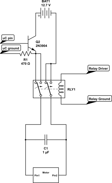
It may be easier and cheaper if you used a DPDT relay to change the direction of the motor. Here is a schematic of what I mean:
schematic

simulate this circuit – Schematic created using CircuitLab

The microcontroller pin you use on the power transistor (labeled Q2 in the schematic) will allow current to flow through the relay, the direction the current moves through the motor is dependant on the state of the relay. I have used this circuit for many projects due to its simplicity, cost, and the inherent robustness of relays.

*Quick note the transistor used in the schematic is not capable of handling 10 amps of current. I have had good fortune with the tip142 darlington pair transistor, the data sheet says it can handle 10 amps continuous current. Datasheet: http://www.alldatasheet.com/datasheet-pdf/pdf/25370/STMICROELECTRONICS/TIP142.html

*Make sure the capacitor you use on the motor can handle many hundreds of volts

*The relay coil will need something to drive it, that can take a few configurations depending on the relay used.

*As for cost, the relay can run up to four or five bucks, same for the transistor.

It may be easier and cheaper if you used a DPDT relay to change the direction of the motor. Here is a schematic of what I mean:

schematic

simulate this circuit – Schematic created using CircuitLab

The microcontroller pin you use on the power transistor (labeled Q2 in the schematic) will allow current to flow through the relay, the direction the current moves through the motor is dependant on the state of the relay. I have used this circuit for many projects due to its simplicity, cost, and the inherent robustness of relays.

*Quick note the transistor used in the schematic is not capable of handling 10 amps of current.

*Make sure the capacitor you use on the motor can handle many hundreds of volts

*The relay coil will need something to drive it, that can take a few configurations depending on the relay used.

It may be easier and cheaper if you used a DPDT relay to change the direction of the motor. Here is a schematic of what I mean:

schematic

simulate this circuit – Schematic created using CircuitLab

The microcontroller pin you use on the power transistor (labeled Q2 in the schematic) will allow current to flow through the relay, the direction the current moves through the motor is dependant on the state of the relay. I have used this circuit for many projects due to its simplicity, cost, and the inherent robustness of relays.

*Quick note the transistor used in the schematic is not capable of handling 10 amps of current. I have had good fortune with the tip142 darlington pair transistor, the data sheet says it can handle 10 amps continuous current. Datasheet: http://www.alldatasheet.com/datasheet-pdf/pdf/25370/STMICROELECTRONICS/TIP142.html

*Make sure the capacitor you use on the motor can handle many hundreds of volts

*The relay coil will need something to drive it, that can take a few configurations depending on the relay used.

*As for cost, the relay can run up to four or five bucks, same for the transistor.

Source Link

It may be easier and cheaper if you used a DPDT relay to change the direction of the motor. Here is a schematic of what I mean:

schematic

simulate this circuit – Schematic created using CircuitLab

The microcontroller pin you use on the power transistor (labeled Q2 in the schematic) will allow current to flow through the relay, the direction the current moves through the motor is dependant on the state of the relay. I have used this circuit for many projects due to its simplicity, cost, and the inherent robustness of relays.

*Quick note the transistor used in the schematic is not capable of handling 10 amps of current.

*Make sure the capacitor you use on the motor can handle many hundreds of volts

*The relay coil will need something to drive it, that can take a few configurations depending on the relay used.