added 10 characters in body
Source Link
winny
  • 16.8k
  • 6
  • 50
  • 71

To explain the application, you have a microcontroller (ESP-32 in this case) powered by a 5V5 V wall adapter and it performs its normal operations ONLY when powered by the 5v+5+ V wall adapter.

I want to use a non-inverting comparator for this application, in order to send a digital signal to the MCU that the wall adapter is either ON, or OFF. I have created this using an open drain TL331 comparator and a 2.5v5 V fixed reference (using a TL341).

When the wall adapter voltage is above a voltage threshold of around 4.6V6 V (set by the voltage divider), then the open collector output turns LOW, and the MCU's input pin goes LOW.

When the wall voltage goes below the 4.6V6 V threshold, then the open collector output is disconnected, and the microcontroller registers a HIGH signal, through a pull-up resistor.

The non-inverting comparator and the 2.5v5 V reference are ONLY powered through the 5V5 V wall adapter, so as to prevent it from draining the battery when the microcontroller is in deep sleep. The 2 ORing diodes (D1 and D2) prevent the battery from ever powering the comparator.

An inverting comparator (with open collector output) would not work in this case, as you would need to send the MCU a LOW signal when the voltage is below 4.6V6 V, however, because the comparator is being powered by the wall adapter itself, the low signal will stop being sent once the wall adapter is completely switched off, as the comparator will be unpowered.

The original schematic uses diode's (1N4001) which could cause too much of a voltage drop for the 4.5v5 V battery. Therefore, I have changed the circuit to include a Schottky diode and a logic level P-channel mosfet, based on a PSU switching circuit I am familiar with. This will ensure only a very low voltage drop for the battery over it's entire voltage range. source of this circuit: https://electronics.stackexchange.com/a/418277/306786

Based on Andyaka's suggestions, I think it would be better to go with a sub-microamp comparator (e.g. MCP6546) & reference (e.g. MAX6006), which are both continually powered by the 3.3v3 V low Q.I. regulator. The comparator can now be inverting, instead of non-inverting and hysteresis can be added with the resistor RH. Here is my basic thoughts for now, without doing any hysteresis calculations yet.

To explain the application, you have a microcontroller (ESP-32 in this case) powered by a 5V wall adapter and it performs its normal operations ONLY when powered by the 5v+ wall adapter.

I want to use a non-inverting comparator for this application, in order to send a digital signal to the MCU that the wall adapter is either ON, or OFF. I have created this using an open drain TL331 comparator and a 2.5v fixed reference (using a TL341).

When the wall adapter voltage is above a voltage threshold of around 4.6V (set by the voltage divider), then the open collector output turns LOW, and the MCU's input pin goes LOW.

When the wall voltage goes below the 4.6V threshold, then the open collector output is disconnected, and the microcontroller registers a HIGH signal, through a pull-up resistor.

The non-inverting comparator and the 2.5v reference are ONLY powered through the 5V wall adapter, so as to prevent it from draining the battery when the microcontroller is in deep sleep. The 2 ORing diodes (D1 and D2) prevent the battery from ever powering the comparator.

An inverting comparator (with open collector output) would not work in this case, as you would need to send the MCU a LOW signal when the voltage is below 4.6V, however, because the comparator is being powered by the wall adapter itself, the low signal will stop being sent once the wall adapter is completely switched off, as the comparator will be unpowered.

The original schematic uses diode's (1N4001) which could cause too much of a voltage drop for the 4.5v battery. Therefore, I have changed the circuit to include a Schottky diode and a logic level P-channel mosfet, based on a PSU switching circuit I am familiar with. This will ensure only a very low voltage drop for the battery over it's entire voltage range. source of this circuit: https://electronics.stackexchange.com/a/418277/306786

Based on Andyaka's suggestions, I think it would be better to go with a sub-microamp comparator (e.g. MCP6546) & reference (e.g. MAX6006), which are both continually powered by the 3.3v low Q.I. regulator. The comparator can now be inverting, instead of non-inverting and hysteresis can be added with the resistor RH. Here is my basic thoughts for now, without doing any hysteresis calculations yet.

To explain the application, you have a microcontroller (ESP-32 in this case) powered by a 5 V wall adapter and it performs its normal operations ONLY when powered by the 5+ V wall adapter.

I want to use a non-inverting comparator for this application, in order to send a digital signal to the MCU that the wall adapter is either ON, or OFF. I have created this using an open drain TL331 comparator and a 2.5 V fixed reference (using a TL341).

When the wall adapter voltage is above a voltage threshold of around 4.6 V (set by the voltage divider), then the open collector output turns LOW, and the MCU's input pin goes LOW.

When the wall voltage goes below the 4.6 V threshold, then the open collector output is disconnected, and the microcontroller registers a HIGH signal, through a pull-up resistor.

The non-inverting comparator and the 2.5 V reference are ONLY powered through the 5 V wall adapter, so as to prevent it from draining the battery when the microcontroller is in deep sleep. The 2 ORing diodes (D1 and D2) prevent the battery from ever powering the comparator.

An inverting comparator (with open collector output) would not work in this case, as you would need to send the MCU a LOW signal when the voltage is below 4.6 V, however, because the comparator is being powered by the wall adapter itself, the low signal will stop being sent once the wall adapter is completely switched off, as the comparator will be unpowered.

The original schematic uses diode's (1N4001) which could cause too much of a voltage drop for the 4.5 V battery. Therefore, I have changed the circuit to include a Schottky diode and a logic level P-channel mosfet, based on a PSU switching circuit I am familiar with. This will ensure only a very low voltage drop for the battery over it's entire voltage range. source of this circuit: https://electronics.stackexchange.com/a/418277/306786

Based on Andyaka's suggestions, I think it would be better to go with a sub-microamp comparator (e.g. MCP6546) & reference (e.g. MAX6006), which are both continually powered by the 3.3 V low Q.I. regulator. The comparator can now be inverting, instead of non-inverting and hysteresis can be added with the resistor RH. Here is my basic thoughts for now, without doing any hysteresis calculations yet.

deleted 373 characters in body
Source Link

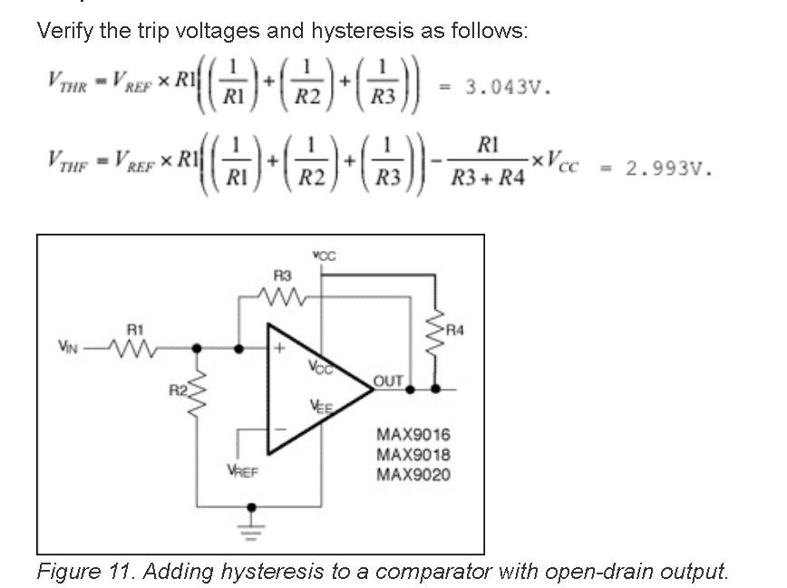
UPDATE 2: To calculate the hysteresis width for my latest schematic, I'm assuming that the below calculation would be suitable for my application, with a fixed reference voltage at the inverting input? VOL and VOH appear to be the voltage at the output of the comparator, when thean open collector output is ON (VOL) and OFF (VOH). Can I simply do measurement's for both VOL and VOH with a cheap multimeter and then plug those value's into the equationdrain comparator? Thanks!

Update 3: Wondering if I can just assume that VOL will be 0v, as the open collector is switched directly to ground, and VOH will be about 3.3v or slightly less, as the internal pull-up resistor of esp32 will be much weaker than the hysteresis resistor?enter image description here

enter image description hereSource of calculations

UPDATE 2: To calculate the hysteresis width for my latest schematic, I'm assuming that the below calculation would be suitable for my application, with a fixed reference voltage at the inverting input? VOL and VOH appear to be the voltage at the output of the comparator, when the open collector output is ON (VOL) and OFF (VOH). Can I simply do measurement's for both VOL and VOH with a cheap multimeter and then plug those value's into the equation? Thanks!

Update 3: Wondering if I can just assume that VOL will be 0v, as the open collector is switched directly to ground, and VOH will be about 3.3v or slightly less, as the internal pull-up resistor of esp32 will be much weaker than the hysteresis resistor?

enter image description here

UPDATE 2: To calculate the hysteresis width for my latest schematic, I'm assuming that the below calculation would be suitable for my application, with a fixed reference voltage at the inverting input and an open drain comparator?

enter image description here

Source of calculations

added 247 characters in body
Source Link

Update 3: Wondering if I can just assume that VOL will be 0v, as the open collector is switched directly to ground, and VOH will be about 3.3v or slightly less, as the internal pull-up resistor of esp32 will be much weaker than the hysteresis resistor?

enter image description here

enter image description here

Update 3: Wondering if I can just assume that VOL will be 0v, as the open collector is switched directly to ground, and VOH will be about 3.3v or slightly less, as the internal pull-up resistor of esp32 will be much weaker than the hysteresis resistor?

enter image description here

added 291 characters in body
Source Link
Loading
added 9 characters in body
Source Link
Loading
added 10 characters in body
Source Link
Loading
added 717 characters in body
Source Link
Loading
added 529 characters in body
Source Link
Loading
Source Link
Loading