removed paragraph about power transfer since electret microphones are biased with DC. Stick with AC signals.
Source Link
glen_geek
  • 27.6k
  • 1
  • 25
  • 56

An attempt to clear up a misunderstanding - hope it doesn't cause more confusion...

But now I don't understand how it works with the microphone. If the "Microphone" is (+ pole) and "Ground" is still (- pole), where is the signal transported to? Is the microphone signal transported into "Ground" (- pole)? Or the "Microphone" (+ pole), but the current does not flow in that direction.

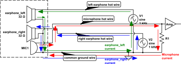
Perhaps a misunderstanding is that current flows always in loops - complete loops - from a source. In this system, there are three sources: two are at one end of the cable (right & left voltage sources V2, V1) while the third is at the other end of the cable (microphone MIC1). Sources at opposite ends seems to be causing confusion.
schematic

simulate this circuit – Schematic created using CircuitLab


With three sources, the common ground line carries three currents, all mingling together and adding/subtracting linearly. The three "hot lines" (microphone, left, right) carry individual currents so that unlike ground, no mingling...the right earphone hot-line only carries current for the right earphone.

Current direction is shown at a particular moment - be aware that direction changes with time, since voltage waveform from each source generates alternating currents.
Perhaps the OP is thinking of power transfer. The microphone MIC1 is a source of power - power flow is always from microphone to R1...current loop direction changes from moment-to-moment along with voltage polarity to ensure that power flows always from MIC1 source to R1 load.

The fact that the common ground carries three currents can be a problem if this wire resistance is too high - in this case, it is possible that the microphone amplifier might see some of the left and right signals. You might see a robust, thick ground wire in an effort to reduce its resistance so that co-mingling signal currents generate very little voltage along its length.

An attempt to clear up a misunderstanding - hope it doesn't cause more confusion...

But now I don't understand how it works with the microphone. If the "Microphone" is (+ pole) and "Ground" is still (- pole), where is the signal transported to? Is the microphone signal transported into "Ground" (- pole)? Or the "Microphone" (+ pole), but the current does not flow in that direction.

Perhaps a misunderstanding is that current flows always in loops - complete loops - from a source. In this system, there are three sources: two are at one end of the cable (right & left voltage sources V2, V1) while the third is at the other end of the cable (microphone MIC1). Sources at opposite ends seems to be causing confusion.

schematic

simulate this circuit – Schematic created using CircuitLab


With three sources, the common ground line carries three currents, all mingling together and adding/subtracting linearly. The three "hot lines" (microphone, left, right) carry individual currents so that unlike ground, no mingling...the right earphone hot-line only carries current for the right earphone.

Current direction is shown at a particular moment - be aware that direction changes with time, since voltage waveform from each source generates alternating currents.

The fact that the common ground carries three currents can be a problem if this wire resistance is too high - in this case, it is possible that the microphone amplifier might see some of the left and right signals. You might see a robust, thick ground wire in an effort to reduce its resistance so that co-mingling signal currents generate very little voltage along its length.

Source Link
glen_geek
  • 27.6k
  • 1
  • 25
  • 56

An attempt to clear up a misunderstanding - hope it doesn't cause more confusion...

But now I don't understand how it works with the microphone. If the "Microphone" is (+ pole) and "Ground" is still (- pole), where is the signal transported to? Is the microphone signal transported into "Ground" (- pole)? Or the "Microphone" (+ pole), but the current does not flow in that direction.

Perhaps a misunderstanding is that current flows always in loops - complete loops - from a source. In this system, there are three sources: two are at one end of the cable (right & left voltage sources V2, V1) while the third is at the other end of the cable (microphone MIC1). Sources at opposite ends seems to be causing confusion.

schematic

simulate this circuit – Schematic created using CircuitLab


With three sources, the common ground line carries three currents, all mingling together and adding/subtracting linearly. The three "hot lines" (microphone, left, right) carry individual currents so that unlike ground, no mingling...the right earphone hot-line only carries current for the right earphone.

Current direction is shown at a particular moment - be aware that direction changes with time, since voltage waveform from each source generates alternating currents.
Perhaps the OP is thinking of power transfer. The microphone MIC1 is a source of power - power flow is always from microphone to R1...current loop direction changes from moment-to-moment along with voltage polarity to ensure that power flows always from MIC1 source to R1 load.

The fact that the common ground carries three currents can be a problem if this wire resistance is too high - in this case, it is possible that the microphone amplifier might see some of the left and right signals. You might see a robust, thick ground wire in an effort to reduce its resistance so that co-mingling signal currents generate very little voltage along its length.