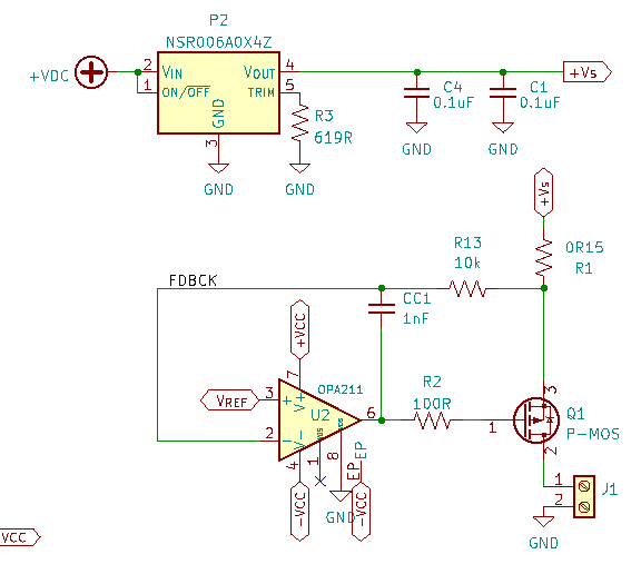
I'm using an NSR006A0X4Z DC/DC with 12V input and set to produce 2.5V output (Rtrim = 619Ω).
This is used for a current source, controlled by GPIOs of a Raspb Pi:

The op-amp is powered with ±5V. The output (power) transistor is the SPP80P06P H, with a Vthreshold of 4V max (well, ‒4V, being p-channel).
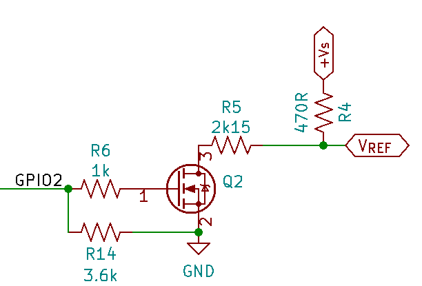
VREF is generated through the GPIOs; the following is a simplified version of it:
With GPIO2 at 0, VREF = Vs, which I confirmed is 2.5V (well, 2.498V according to the multimeter), and this produces an output current of 0A. When setting GPIO2 to 1, VREF is supposed to be set at 2.05V, producing an output current of 3A.
However, the output current is lower (approx. 2.76A) because Vs drops to approx. 2.43V.
The "upstream" power source (+VDC in the schematic) comes from a wall adapter that specifies an output of 12V / 3.6A max.
The only detail the NSR006A0X4Z datasheet says that could explain is the external output capacitor, which as they put it, "reduce the output ripple and improve the dynamic response to a step load change". Since I am "instantly" (well, as instantly as the circuit allows) switching from 0A to 3A, I thought that might be it. I added a 100uF/16V Aluminum Polymer capacitor at the output (soldered it right at the converter's output pin, with the other pin soldered to a ground plane copper pour). No change.
The behavior seems consistent; not only have I tried two different boards and observed essentially identical results; one of the boards originally had the OKR-T-10-W12, and we switched to the NSR006A0x4Z because the OKR went out-of-stock. But the issue was essentially identical with the OKR-T-10-W12 (albeit, the board that had the OKR never had the 100uF capacitor at the output).
Any ideas why?

