added 23 characters in body
Source Link
ocrdu
  • 9.3k
  • 23
  • 32
  • 42

We have to interface with thea device that is expecting a chain of 34 OhmΩ resistors with switches connected to the input pins as shown below. 

There is no information on the internal schematics of the device, but there is 10V10 V present on the open circuit and when shorted the current is limited to 5mA5 mA. The documentation mentions "maximum input voltage 34V"34 V", which is weird, since we are not expected to supply voltage to those pins.

enter image description here

My first thought was to simply emulate the suggested circuit with analog switches (like ADG715) and a bunch of resistors. Then I thought of digital potentiometers (like AD5254), that do not need resistors.

The problem, however, is that all these chips have analog voltage limits pretty close to their digital supply lines. So, it seems I need either a way to add a high voltage-voltage-tolerant output stage to the digital pot, or use a completely different approach, like a DAC + VCR (voltage controlled resistor). Unfortunately analog analog circuits are still my weak spot,spot; I'm not sure I can design a FET-based linear VCR properly.

Any other options I have missed? I should also mention that simplifying the circuit and reducing cost are important to us.

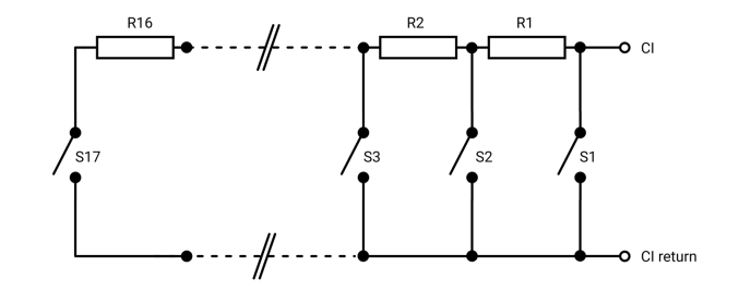
We have to interface with the device that is expecting a chain of 34 Ohm resistors with switches connected to the input pins as shown below. There is no information on the internal schematics of the device, but there is 10V present on the open circuit and when shorted the current is limited to 5mA. The documentation mentions "maximum input voltage 34V", which is weird, since we are not expected to supply voltage to those pins.

enter image description here

My first thought was to simply emulate the suggested circuit with analog switches (like ADG715) and a bunch of resistors. Then I thought of digital potentiometers (like AD5254), that do not need resistors.

The problem, however, is that all these chips have analog voltage limits pretty close to their digital supply lines. So, it seems I need either a way to add high voltage-tolerant output stage to digital pot, or use completely different approach, like DAC + VCR (voltage controlled resistor). Unfortunately analog circuits are still my weak spot, not sure I can design FET-based linear VCR properly.

Any other options I have missed? I should also mention that simplifying the circuit and reducing cost are important to us.

We have to interface with a device that is expecting a chain of 34 Ω resistors with switches connected to the input pins as shown below. 

There is no information on the internal schematics of the device, but there is 10 V present on the open circuit and when shorted the current is limited to 5 mA. The documentation mentions "maximum input voltage 34 V", which is weird, since we are not expected to supply voltage to those pins.

enter image description here

My first thought was to simply emulate the suggested circuit with analog switches (like ADG715) and a bunch of resistors. Then I thought of digital potentiometers (like AD5254), that do not need resistors.

The problem, however, is that all these chips have analog voltage limits pretty close to their digital supply lines. So, it seems I need either a way to add a high-voltage-tolerant output stage to the digital pot, or use a completely different approach, like a DAC + VCR (voltage controlled resistor). Unfortunately analog circuits are still my weak spot; I'm not sure I can design a FET-based linear VCR properly.

Any other options I have missed? I should also mention that simplifying the circuit and reducing cost are important to us.

Tweeted twitter.com/StackElectronix/status/1605941228066971648
Became Hot Network Question
added 88 characters in body
Source Link
Maple
  • 13.1k
  • 2
  • 26
  • 63

We have to interface with the device that is expecting a chain of 34 Ohm resistors with switches connected to the input pins as shown below. There is no information on the internal schematics of the device, but there is 10V present on the open circuit and when shorted the current is limited to 5mA. The documentation mentions "maximum input voltage 34V", which is weird, since we are not expected to supply voltage to those pins.

enter image description here

My first thought was to simply emulate the suggested circuit with analog switches (like ADG715) and a bunch of resistors. Then I thought of digital potentiometers (like AD5254), that do not need resistors.

The problem, however, is that all these chips have analog voltage limits pretty close to their digital supply lines. So, it seems I need either a way to add high voltage-tolerant output stage to digital pot, or use completely different approach, like DAC + VCR (voltage controlled resistor). Unfortunately analog circuits are still my weak spot, not sure I can design FET-based linear VCR properly.

Any other options I have missed? I should also mention that simplifying the circuit and reducing cost are important to us.

We have to interface with the device that is expecting a chain of 34 Ohm resistors with switches connected to the input pins as shown below. There is no information on the internal schematics of the device, but there is 10V present on the open circuit and when shorted the current is limited to 5mA. The documentation mentions "maximum input voltage 34V", which is weird, since we are not expected to supply voltage to those pins.

enter image description here

My first thought was to simply emulate the suggested circuit with analog switches (like ADG715) and a bunch of resistors. Then I thought of digital potentiometers (like AD5254), that do not need resistors.

The problem, however, is that all these chips have analog voltage limits pretty close to their digital supply lines. So, it seems I need either a way to add high voltage-tolerant output stage to digital pot, or use completely different approach, like DAC + VCR (voltage controlled resistor). Unfortunately analog circuits are still my weak spot, not sure I can design FET-based linear VCR properly.

Any other options I have missed?

We have to interface with the device that is expecting a chain of 34 Ohm resistors with switches connected to the input pins as shown below. There is no information on the internal schematics of the device, but there is 10V present on the open circuit and when shorted the current is limited to 5mA. The documentation mentions "maximum input voltage 34V", which is weird, since we are not expected to supply voltage to those pins.

enter image description here

My first thought was to simply emulate the suggested circuit with analog switches (like ADG715) and a bunch of resistors. Then I thought of digital potentiometers (like AD5254), that do not need resistors.

The problem, however, is that all these chips have analog voltage limits pretty close to their digital supply lines. So, it seems I need either a way to add high voltage-tolerant output stage to digital pot, or use completely different approach, like DAC + VCR (voltage controlled resistor). Unfortunately analog circuits are still my weak spot, not sure I can design FET-based linear VCR properly.

Any other options I have missed? I should also mention that simplifying the circuit and reducing cost are important to us.

Source Link
Maple
  • 13.1k
  • 2
  • 26
  • 63

Resistor chain substitute

We have to interface with the device that is expecting a chain of 34 Ohm resistors with switches connected to the input pins as shown below. There is no information on the internal schematics of the device, but there is 10V present on the open circuit and when shorted the current is limited to 5mA. The documentation mentions "maximum input voltage 34V", which is weird, since we are not expected to supply voltage to those pins.

enter image description here

My first thought was to simply emulate the suggested circuit with analog switches (like ADG715) and a bunch of resistors. Then I thought of digital potentiometers (like AD5254), that do not need resistors.

The problem, however, is that all these chips have analog voltage limits pretty close to their digital supply lines. So, it seems I need either a way to add high voltage-tolerant output stage to digital pot, or use completely different approach, like DAC + VCR (voltage controlled resistor). Unfortunately analog circuits are still my weak spot, not sure I can design FET-based linear VCR properly.

Any other options I have missed?