While designing a Raspberry Pi CM4 application board, I found an issue with the power supply.
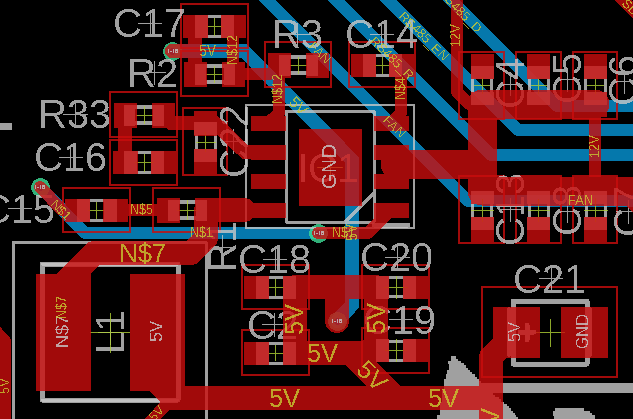
I selected the same IC as the official CM4 I/O board: the AP64501SP-13. I used even the same values for a 5V5 V regulator and tried to place the components on the board following a similar layout and respecting the IC recommendations: minimizing the distances between the components (input capacitors and input of the IC,), solid ground, shortest traces, etc.
There are two issues. Maybe someone with experience with this IC (or in the field) could give me a hint:
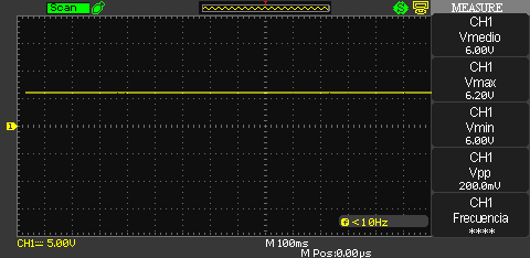
- Without load, the regulated output voltage does not match the expected 5V, but instead it gives 6V. This is not too much of a problem.
Without load, the regulated output voltage does not match the expected 5 V, but instead it gives 6 V. This is not too much of a problem.
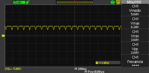
With the CM4 connected, the output voltage starts producing an inadmissible ripple that messes up the CM4.
- With the CM4 connected, the output voltage starts producing an inadmissible ripple that messes up the CM4.


