added 731 characters in body
Source Link

For example, if an ohm function range uses a \$1\mu A\$1μA test current, then it can be used to measure resistors with a value of about 0.5V \$ 0.5V / 1 \mu A = 500k\Omega \$/ 1μA = 500kΩ without turning on silicon PN junctions, which turn on at about \$0.6V\$0.6V (you would need still smaller currents to measure the same resistance without turning on Schottky or Germanium diodes).

E.g., the same \$1\mu A\$1μA current above will generate a scant \$10\mu V\$voltage10μV voltage drop across a \$10\Omega\$10Ω resistor, voltage which is down in the noise in most situations and requires quite a sophisticated (and expensive) measurement circuitry.

For example, with a \$1 mA\$1mA test current it is sufficient to have \$500\Omega\$500Ω of resistance across the probe terminals to generate a \$500mV\$500mV drop, which is enough to bring silicon diodes in conduction (and more so Schottky or germanium diodes). This will clamp the voltage to that value, making the DMM show you a \$500mV / 1mA = 500\Omega\$500mV/1mA = 500Ω value on the display.

If you want to check if this is really your case, try and measure with another DMM the test current put out by your original DMM on its continuity function. If it measures \$\sim\!1mA\$about 1mA you have a high chance that during the continuity measurement you turned on some semiconductor junction.

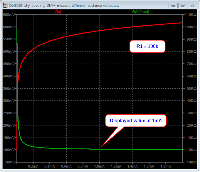
Now, since you said you measured 100kΩ with the resistance function, I was curious to reproduce it in the simulation, changingso I changed R1 to 100k. Here are the results:

For example, if an ohm function range uses a \$1\mu A\$ test current, then it can be used to measure resistors with a value of about \$ 0.5V / 1 \mu A = 500k\Omega \$ without turning on silicon PN junctions, which turn on at about \$0.6V\$ (you would need still smaller currents to measure the same resistance without turning on Schottky or Germanium diodes).

E.g., the same \$1\mu A\$ current above will generate a scant \$10\mu V\$voltage drop across a \$10\Omega\$ resistor, voltage which is down in the noise in most situations and requires quite a sophisticated (and expensive) measurement circuitry.

For example, with a \$1 mA\$ test current it is sufficient to have \$500\Omega\$ of resistance across the probe terminals to generate a \$500mV\$ drop, which is enough to bring silicon diodes in conduction (and more so Schottky or germanium diodes). This will clamp the voltage to that value, making the DMM show you a \$500mV / 1mA = 500\Omega\$ value on the display.

If you want to check if this is really your case, try and measure with another DMM the test current put out by your original DMM on its continuity function. If it measures \$\sim\!1mA\$ you have a high chance that during the continuity measurement you turned on some semiconductor junction.

Now, since you said you measured 100kΩ with the resistance function, I was curious to reproduce it in the simulation, changing R1 to 100k. Here are the results:

For example, if an ohm function range uses a 1μA test current, then it can be used to measure resistors with a value of about 0.5V / 1μA = 500kΩ without turning on silicon PN junctions, which turn on at about 0.6V (you would need still smaller currents to measure the same resistance without turning on Schottky or Germanium diodes).

E.g., the same 1μA current above will generate a scant 10μV voltage drop across a 10Ω resistor, voltage which is down in the noise in most situations and requires quite a sophisticated (and expensive) measurement circuitry.

For example, with a 1mA test current it is sufficient to have 500Ω of resistance across the probe terminals to generate a 500mV drop, which is enough to bring silicon diodes in conduction (and more so Schottky or germanium diodes). This will clamp the voltage to that value, making the DMM show you a 500mV/1mA = 500Ω value on the display.

If you want to check if this is really your case, try and measure with another DMM the test current put out by your original DMM on its continuity function. If it measures about 1mA you have a high chance that during the continuity measurement you turned on some semiconductor junction.

Now, since you said you measured 100kΩ with the resistance function, I was curious to reproduce it in the simulation, so I changed R1 to 100k. Here are the results:
added 731 characters in body
Source Link

Now, since you said you measured 100kΩ with the resistance function, I was curious to reproduce it in the simulation, changing R1 to 100k. Here are the results:

enter image description here

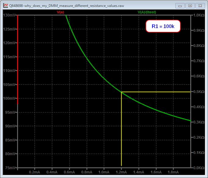
which is pretty unreadable, but zooming in gives this picture:

enter image description here

I have added the yellow lines, which highlight that you would get a reading of 500Ω with a test current of about 1.2mA, which may be coherent with your situation.

I'd really like to hear you back telling us what test current value your DMM actually generates, as a definitive confirmation of my hypothesis.

added 43 characters in body
Source Link

As you can see, when the current is low enough, the DMM displays the correct value (thatof 500Ω, i.e. that of the resistor R)R1. Once the current reaches some high enough valueabout 0.7mA D1 begins to turn on, the voltage at A is clamped to about 0.6V and the displayed value decreases.

As you can see, when the current is low enough, the DMM displays the correct value (that of the resistor R). Once the current reaches some high enough value, the voltage at A is clamped and the displayed value decreases.

As you can see, when the current is low enough, the DMM displays the correct value of 500Ω, i.e. that of the resistor R1. Once the current reaches about 0.7mA D1 begins to turn on, the voltage at A is clamped to about 0.6V and the displayed value decreases.

added 459 characters in body
Source Link
Loading
added 669 characters in body
Source Link
Loading
added 83 characters in body
Source Link
Loading
Source Link
Loading