1 - Why the Capacitance Multiplier has a better response ‘filtering’
the higher frequencies
The very low quiescent current of the MCP1700 suggests that \$gain \times bandwidth\$ product is not wonderful. Indeed, at 10 kHz., line regulation sucks...data sheet suggests that output ripple should be about half input ripple.
\$\beta\$ of the capacitor-multiplier at 10 kHz. is pretty-much identical to \$\beta\$ at 100 Hz. Ripple rejection of its RC filter should improve as frequency goes up, at least to a few MHz, where \$\beta\$ starts to fall off.
2 - Regarding noise and ripple suppression can a CM circuit be
considered as good as (or better than) common (aka jelly bean) series
voltage regulators?
Keep in mind that capacitor-multiplier filtering ripple rejection is dominated by its RC low-pass filter, so low-frequency filtering should be inferior to a properly designed active regulator. Even with \$\beta multiplication\$ a very large RC product is needed to filter low frequency ripple.
As for low-amplitude noise, many transistors (especially the physically-larger ones) have lower intrinsic noise sources than the op-amp-like gain stages inside active regulators...especially if you consider 1/f noise at really-low frequencies.
Trying to filter-out this really-low-frequency noise with a shunt capacitor attached to an active regulator's output is nearly impossible, because output impedance is often a fraction of an ohm. This output-shunt capacitor only starts to be effective when the internal gain stage of the active regulator drops-off at high frequency (perhaps above 10 kHz).
Dave mentions in his blog that ripple rejection of capacitor-multiplier circuit can be quite good, but stresses that load regulation is terrible when compared with an active regulator like LM317.
As for switching regulators, consider noise at frequencies not related to switching frequency and its harmonics. Noise floor performance in this context can be as good as linear regulators.
3 - Could the above behavior be seen as “less frequency-dependent”
response of the CM and be extended to 100 KHz or more? If not, which
would be the limitations expected?
Above 100kHz, a shunt capacitor adjacent to the load should be considered superior. Inductance of conductor paths between regulator and load (and back) become significant.
As for the capacitor-multiplier circuit, equivalent-series-resistance of the (electrolytic) capacitor becomes significant at some point.
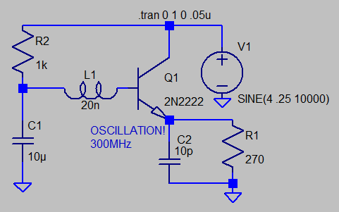
Dave also misses the nasty tendency of the capacitor-multiplier circuit to oscillate at very high (VHF) or ultra-high (UHF) frequencies. Take a closer look at OP's upper-right photo of Dave's test circuit. It shows a fuzz on top of output waveform. This fuzz could possibly be oscillations at hundreds of MHz. Tiny inductances in the base and/or emitter have not been accounted for that cause oscillation. Oscillation amplitude is often small and easy to miss. In actual use, I have often found this simple capacitor-multiplier oscillating - but a good quality 'scope doesn't show it. Ferrite beads on base and/or emitter might be needed.
4 - Could the CM (all 3 variants shown above) be seen as an Open-loop
circuit of current-amplified ripple suppression?
Be careful here - you're assuming linear circuit operation. Consider that a down-stream capacitor often exists. This capacitor-multiplier circuit can only source current, and cannot sink current. A non-linear load can suddenly disappear, or even rise in voltage momentarily. Transistor current falls to zero.
Many active regulators suffer the same problem, but since their load regulation is often far superior to capacitor-multiplier circuit, the consequences are less-dire.
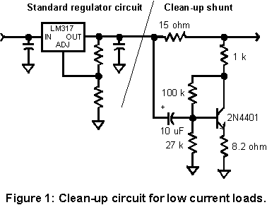
An alternative noise-reducing post-regulator circuit:
Charles Wenzel offered this feed-forward noise cancel circuit. Like a capacitor-multiplier, load regulation is not great. Unlike a capacitor-multiplier, AC noise is amplified, inverted, and current is added to output so that very low-amplitude noise is attenuated. It can improve noise performance of many linear regulators.


