added 34 characters in body
Source Link
ocrdu
  • 9.3k
  • 23
  • 32
  • 42

I have a circuit which includes two back to back-to-back switching regulators. The first is used to take the input of 14V14 V to 5V5 V and the second charges a 2 cell-cell lithium battery. I

I have verified the problem to be with the first regulator. II cut the connection between the Vout of the 14V14 V to 5V5 V regulator and supplied the second regulator with a constant 5V5 V and it worked as intended.

The problem with the 14V14 V to 5V5 V regulator seems to be instability and a changing nominal output voltage. At 6VAt 6 V Vin the regulator is outputting something close to 5V5 V, but as the input voltage increases (even to just 14V14 V), so does the instability and the nominal output voltage increases above 6V6 V which is too high for my application. The

The ICs on the output side are outputting over voltageovervoltage protection at about 6V6 V. OnOn the instability, I see the output voltage on the oscope having +/- 0.7V7 V on the nominal output voltage. I have fried my IC during testing, but can solder a new one on here shortly.

Why would the nominal output voltage of this regulator potentially rise with input voltage? If I add more capacitance on the output voltage will it smooth the output signal and prevent these voltage fluctuations?

circuit

Datasheets: 
RFN1LAM6STFTR 
MAX20077ATCA_VY+ 
SF-1206SA150M-2 
SRP3212-2R2M 
865080340001 
865230443003 
CNC5L1X7R1C106K160AE

circuit from datasheet

layout

regulator properties

I have a circuit which includes two back to back switching regulators. The first is used to take the input of 14V to 5V and the second charges a 2 cell lithium battery. I have verified the problem to be with the first regulator. I cut the connection between the Vout of the 14V to 5V regulator and supplied the second regulator with a constant 5V and it worked as intended.

The problem with the 14V to 5V regulator seems to be instability and a changing nominal output voltage. At 6V Vin the regulator is outputting something close to 5V but as the input voltage increases (even to just 14V), so does instability and the nominal output voltage increases above 6V which is too high for my application. The ICs on the output side are outputting over voltage protection at about 6V. On the instability, I see the output voltage on the oscope having +/- 0.7V on the nominal output voltage. I have fried my IC during testing, but can solder a new one on here shortly.

Why would the nominal output voltage of this regulator potentially rise with input voltage? If I add more capacitance on the output voltage will it smooth the output signal and prevent these voltage fluctuations?

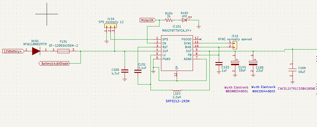
circuit

Datasheets: RFN1LAM6STFTR MAX20077ATCA_VY+ SF-1206SA150M-2 SRP3212-2R2M 865080340001 865230443003 CNC5L1X7R1C106K160AE
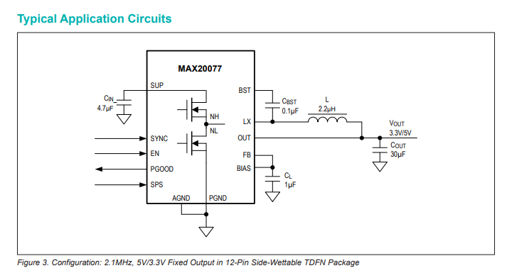
circuit from datasheet

layout

regulator properties

I have a circuit which includes two back-to-back switching regulators. The first is used to take the input of 14 V to 5 V and the second charges a 2-cell lithium battery.

I have verified the problem to be with the first regulator. I cut the connection between the Vout of the 14 V to 5 V regulator and supplied the second regulator with a constant 5 V and it worked as intended.

The problem with the 14 V to 5 V regulator seems to be instability and a changing nominal output voltage. At 6 V Vin the regulator is outputting something close to 5 V, but as the input voltage increases (even to just 14 V), so does the instability and the nominal output voltage increases above 6 V which is too high for my application.

The ICs on the output side are outputting overvoltage protection at about 6 V. On the instability, I see the output voltage on the oscope having +/- 0.7 V on the nominal output voltage. I have fried my IC during testing, but can solder a new one on here shortly.

Why would the nominal output voltage of this regulator potentially rise with input voltage? If I add more capacitance on the output voltage will it smooth the output signal and prevent these voltage fluctuations?

circuit

Datasheets: 
RFN1LAM6STFTR 
MAX20077ATCA_VY+ 
SF-1206SA150M-2 
SRP3212-2R2M 
865080340001 
865230443003 
CNC5L1X7R1C106K160AE
circuit from datasheet

layout

regulator properties

added 92 characters in body
Source Link
Feynman137
  • 1.3k
  • 1
  • 11
  • 38

I have a circuit which includes two back to back switching regulators. The first is used to take the input of 14V to 5V and the second charges a 2 cell lithium battery. I have verified the problem to be with the first regulator. I cut the connection between the Vout of the 14V to 5V regulator and supplied the second regulator with a constant 5V and it worked as intended.

The problem with the 14V to 5V regulator seems to be instability and a changing nominal output voltage. At 6V Vin the regulator is outputting something close to 5V but as the input voltage increases (even to just 14V), so does instability and the nominal output voltage increases above 6V which is too high for my application. The ICs on the output side are outputting over voltage protection at about 6V. On the instability, I see the output voltage on the oscope having +/- 0.7V on the nominal output voltage. I have fried my IC during testing, but can solder a new one on here shortly.

Why would the nominal output voltage of this regulator potentially rise with input voltage? If I add more capacitance on the output voltage will it smooth the output signal and prevent these voltage fluctuations?

circuit

Datasheets: RFN1LAM6STFTR MAX20077ATCA_VY+ SF-1206SA150M-2 SRP3212-2R2M 865080340001 865230443003 CNC5L1X7R1C106K160AE
circuit from datasheet

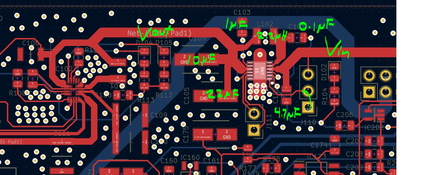
layout

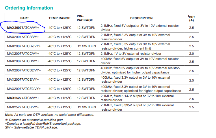
regulator properties

I have a circuit which includes two back to back switching regulators. The first is used to take the input of 14V to 5V and the second charges a 2 cell lithium battery. I have verified the problem to be with the first regulator. I cut the connection between the Vout of the 14V to 5V regulator and supplied the second regulator with a constant 5V and it worked as intended.

The problem with the 14V to 5V regulator seems to be instability and a changing nominal output voltage. At 6V Vin the regulator is outputting something close to 5V but as the input voltage increases (even to just 14V), so does instability and the nominal output voltage increases above 6V which is too high for my application. The ICs on the output side are outputting over voltage protection at about 6V. On the instability, I see the output voltage on the oscope having +/- 0.7V on the nominal output voltage. I have fried my IC during testing, but can solder a new one on here shortly.

Why would the nominal output voltage of this regulator potentially rise with input voltage? If I add more capacitance on the output voltage will it smooth the output signal and prevent these voltage fluctuations?

circuit

Datasheets: RFN1LAM6STFTR MAX20077ATCA_VY+ SF-1206SA150M-2 SRP3212-2R2M 865080340001 865230443003 CNC5L1X7R1C106K160AE
circuit from datasheet

layout

regulator properties

added 68 characters in body
Source Link
Feynman137
  • 1.3k
  • 1
  • 11
  • 38

I have a circuit which includes two back to back switching regulators. The first is used to take the input of 14V to 5V and the second charges a 2 cell lithium battery. I have verified the problem to be with the first regulator. I cut the connection between the Vout of the 14V to 5V regulator and supplied the second regulator with a constant 5V and it worked as intended.

The problem with the 14V to 5V regulator seems to be instability and a changing nominal output voltage. At 6V Vin the regulator is outputting something close to 5V but as the input voltage increases (even to just 14V), so does instability and the nominal output voltage increases above 6V which is too high for my application. The ICs on the output side are outputting over voltage protection at about 6V. On the instability, I see the output voltage on the oscope having +/- 0.7V on the nominal output voltage. I have fried my IC during testing, but can solder a new one on here shortly.

Why would the nominal output voltage of this regulator potentially rise with input voltage? If I add more capacitance on the output voltage will it smooth the output signal and prevent these voltage fluctuations?

circuit

Datasheets: RFN1LAM6STFTR MAX20077ATCA_VY+ SF-1206SA150M-2 SRP3212-2R2M 865080340001 865230443003 CNC5L1X7R1C106K160AE

circuit from datasheet

layout

I have a circuit which includes two back to back switching regulators. The first is used to take the input of 14V to 5V and the second charges a 2 cell lithium battery. I have verified the problem to be with the first regulator. I cut the connection between the Vout of the 14V to 5V regulator and supplied the second regulator with a constant 5V and it worked as intended.

The problem with the 14V to 5V regulator seems to be instability and a changing nominal output voltage. At 6V Vin the regulator is outputting something close to 5V but as the input voltage increases (even to just 14V), so does instability and the nominal output voltage increases above 6V which is too high for my application. The ICs on the output side are outputting over voltage protection at about 6V. On the instability, I see the output voltage on the oscope having +/- 0.7V on the nominal output voltage. I have fried my IC during testing, but can solder a new one on here shortly.

Why would the nominal output voltage of this regulator potentially rise with input voltage? If I add more capacitance on the output voltage will it smooth the output signal and prevent these voltage fluctuations?

circuit

Datasheets: RFN1LAM6STFTR MAX20077ATCA_VY+ SF-1206SA150M-2 SRP3212-2R2M 865080340001 865230443003 CNC5L1X7R1C106K160AE

circuit from datasheet

layout

added 640 characters in body
Source Link
Feynman137
  • 1.3k
  • 1
  • 11
  • 38
Loading
Source Link
Feynman137
  • 1.3k
  • 1
  • 11
  • 38
Loading