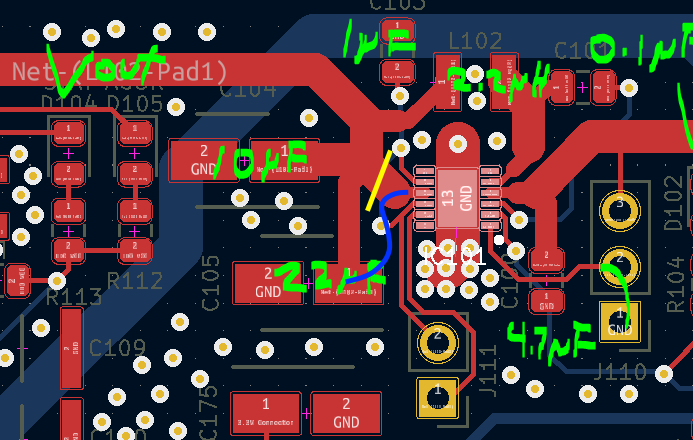
I believe the culprit is the layout of the output node of the IC.
The OUT pin of this chip is really just a sense pin, that closes the loop with the control of the output voltage. The way you have connected it, there is a lot of common path between the OUT pin, and the output side of the inductor.
Imagine all the AC current that is flowing out of the inductor, into the output capacitors: the feedback pin is going to see lots of movement there, missing out on most of the smoothing effect of the caps, because you have hooked it more or less in the mid point.
A better layout would require the feedback signal to have a separate path, ideally connecting directly in the pad of one of the output caps, on a side where no AC current is expected.
It is very well possible that this effect is visible only above a certain input voltage because the duty cycle will be different, and the ripple current in the inductor will change.
One thing you might be able to do to prove this is to cut the track from OUT to the caps, soldering a thin wire to it and connecting it on a location where no AC current is flowing, e.g. on the track going to your charger IC.
In Yellow the cut, in blue a wire going to the pad of a cap.

