Added link to datasheet.
Source Link
SamGibson
  • 18.3k
  • 5
  • 41
  • 63

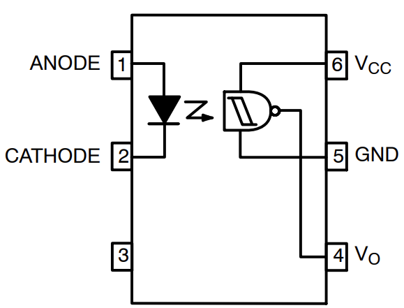
Given the vagueness of the rest of the circuit, I would strongly recommend you use a high sensitivity, logic-level opto-coupler such as an H11L1.

enter image description here

(Logic symbol taken from the onsemi datasheetdatasheet for the H11L1)

On the input side, you are effectively putting another LED and a resistor in parallel with the existing LED and resistor. If you select a high sensitivity coupler, you only need to draw ~1mA, which is probably a fraction of what the existing LED is drawing, and is almost certainly covered by the design margin of the existing setup.

On the receiver side you get a direct logic level output referenced to your ESP32 rails.

Job done.

(Optocouplers are a much overlooked technology, but are used widely in everything from high-side FET drives, to galvanic isolation of comms lines. "Go optocouplers!")

Given the vagueness of the rest of the circuit, I would strongly recommend you use a high sensitivity, logic-level opto-coupler such as an H11L1.

enter image description here

(Logic symbol taken from the onsemi datasheet for the H11L1)

On the input side, you are effectively putting another LED and a resistor in parallel with the existing LED and resistor. If you select a high sensitivity coupler, you only need to draw ~1mA, which is probably a fraction of what the existing LED is drawing, and is almost certainly covered by the design margin of the existing setup.

On the receiver side you get a direct logic level output referenced to your ESP32 rails.

Job done.

(Optocouplers are a much overlooked technology, but are used widely in everything from high-side FET drives, to galvanic isolation of comms lines. "Go optocouplers!")

added 193 characters in body
Source Link
colintd
  • 8.3k
  • 1
  • 13
  • 35

Given the vagueness of the rest of the circuit, I would strongly recommend you use a high sensitivity, logic-level opto-coupler such as an H11L1.

enter image description here

(Logic symbol taken from the onsemi datasheet for the H11L1)

On the input side, you are effectively putting another LED and a resistor in parallel with the existing LED and resistor. If you select a high sensitivity coupler, you only need to draw ~1mA, which is probably a fraction of what the existing LED is drawing, and is almost certainly covered by the design margin of the existing setup.

On the receiver side you get a direct logic level output referenced to your ESP32 rails.

Job done.

(Optocouplers are a much overlooked technology, but are used widely in everything from high-side FET drives, to galvanic isolation of comms lines. "Go optocouplers!")

Given the vagueness of the rest of the circuit, I would strongly recommend you use a high sensitivity, logic-level opto-coupler such as an H11L1.

enter image description here

(Logic symbol taken from the onsemi datasheet for the H11L1)

On the input side, you are effectively putting another LED and a resistor in parallel with the existing LED and resistor. If you select a high sensitivity coupler, you only need to draw ~1mA, which is probably a fraction of what the existing LED is drawing, and is almost certainly covered by the design margin of the existing setup.

On the receiver side you get a direct logic level output referenced to your ESP32 rails.

Job done.

(Optocouplers are a much overlooked technology, but are used widely in everything from high-side FET drives, to galvanic isolation of comms lines. "Go optocouplers!")

Source Link
colintd
  • 8.3k
  • 1
  • 13
  • 35

Given the vagueness of the rest of the circuit, I would strongly recommend you use a high sensitivity, logic-level opto-coupler such as an H11L1.

enter image description here

On the input side, you are effectively putting another LED and a resistor in parallel with the existing LED and resistor. If you select a high sensitivity coupler, you only need to draw ~1mA, which is probably a fraction of what the existing LED is drawing, and is almost certainly covered by the design margin of the existing setup.

On the receiver side you get a direct logic level output referenced to your ESP32 rails.

Job done.

(Optocouplers are a much overlooked technology, but are used widely in everything from high-side FET drives, to galvanic isolation of comms lines. "Go optocouplers!")