added 235 characters in body
Source Link
divB
  • 1.3k
  • 18
  • 38

According to the data sheet, the maximum absolute voltage on a GPIO pin is -0.3 and +4V, respectively and a max of 20mA source/sink. I am trying to understand where these requirements come from and to which extent they apply to my use case:
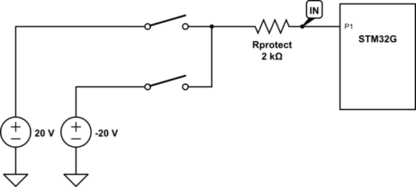
schematic

simulate this circuit – Schematic created using CircuitLab

In this case, if either switch (not both at the same time!) is closed, the maximum current that can flow from/into the GPIO pin is 20/2000=10mA, so within spec.

For the voltage at node "IN" it depends on the resistance looking into the pin. Let's assume this pin drives something, this resistance should be low. But if it's high impedance (e.g. ADC pin), then technically there are +/-20V on this pin. But to which extent can this even be a problem if no current flows?

My understanding is that the IO's still have ESD diodes which clamp high over-voltages. These are thousands of volts but they are a transient (very short) events. What makes the IC susceptible to damage is the current that flows and results in thermal damage. Connecting a 1000V source directly would definitely damage the IC because a large current would flow for long time (heating up junction etc).

But if I add a current limiting resistor to ensure that the maximum current is always below 20mA, I am wondering if the voltage can technically exceed the max absolute ratings under certain conditions.

I know that a Zener diode is the common way to protect a pin. But I am looking for a solution that only uses a resistor (if possible).

Can I connect +/-20V via a 2k resistor to a STM32G GPIO pin?

If not, what is the reason (i.e., the exact damage mechanism)?

If the answer is different depending on the scenario, let's consider the cases (a) device can still operate normally (b) device does not operate normally but does not get permanently damaged (c) device might get permanently damaged

According to the data sheet, the maximum absolute voltage on a GPIO pin is -0.3 and +4V, respectively and a max of 20mA source/sink. I am trying to understand where these requirements come from and to which extent they apply to my use case:

schematic

simulate this circuit – Schematic created using CircuitLab

In this case, if either switch (not both at the same time!) is closed, the maximum current that can flow from/into the GPIO pin is 20/2000=10mA, so within spec.

For the voltage at node "IN" it depends on the resistance looking into the pin. Let's assume this pin drives something, this resistance should be low. But if it's high impedance (e.g. ADC pin), then technically there are +/-20V on this pin. But to which extent can this even be a problem if no current flows?

My understanding is that the IO's still have ESD diodes which clamp high over-voltages. These are thousands of volts but they are a transient (very short) events. What makes the IC susceptible to damage is the current that flows and results in thermal damage. Connecting a 1000V source directly would definitely damage the IC because a large current would flow for long time (heating up junction etc).

But if I add a current limiting resistor to ensure that the maximum current is always below 20mA, I am wondering if the voltage can technically exceed the max absolute ratings under certain conditions.

I know that a Zener diode is the common way to protect a pin. But I am looking for a solution that only uses a resistor (if possible).

Can I connect +/-20V via a 2k resistor to a STM32G GPIO pin?

If not, what is the reason (i.e., the exact damage mechanism)?

If the answer is different depending on the scenario, let's consider the cases (a) device can still operate normally (b) device does not operate normally but does not get permanently damaged (c) device might get permanently damaged

Source Link
divB
  • 1.3k
  • 18
  • 38

Maximum absolute voltage (and currents) on STM32G microcontroller

According to the data sheet, the maximum absolute voltage on a GPIO pin is -0.3 and +4V, respectively and a max of 20mA source/sink. I am trying to understand where these requirements come from and to which extent they apply to my use case:

schematic

simulate this circuit – Schematic created using CircuitLab

In this case, if either switch (not both at the same time!) is closed, the maximum current that can flow from/into the GPIO pin is 20/2000=10mA, so within spec.

For the voltage at node "IN" it depends on the resistance looking into the pin. Let's assume this pin drives something, this resistance should be low. But if it's high impedance (e.g. ADC pin), then technically there are +/-20V on this pin. But to which extent can this even be a problem if no current flows?

My understanding is that the IO's still have ESD diodes which clamp high over-voltages. These are thousands of volts but they are a transient (very short) events. What makes the IC susceptible to damage is the current that flows and results in thermal damage. Connecting a 1000V source directly would definitely damage the IC because a large current would flow for long time (heating up junction etc).

But if I add a current limiting resistor to ensure that the maximum current is always below 20mA, I am wondering if the voltage can technically exceed the max absolute ratings under certain conditions.

I know that a Zener diode is the common way to protect a pin. But I am looking for a solution that only uses a resistor (if possible).

Can I connect +/-20V via a 2k resistor to a STM32G GPIO pin?

If not, what is the reason (i.e., the exact damage mechanism)?