added 129 characters in body
Source Link
Andy aka
  • 473.1k
  • 29
  • 383
  • 839

What's the purpose of the MOSFET on the output of the flyback buck converter in this circuit?

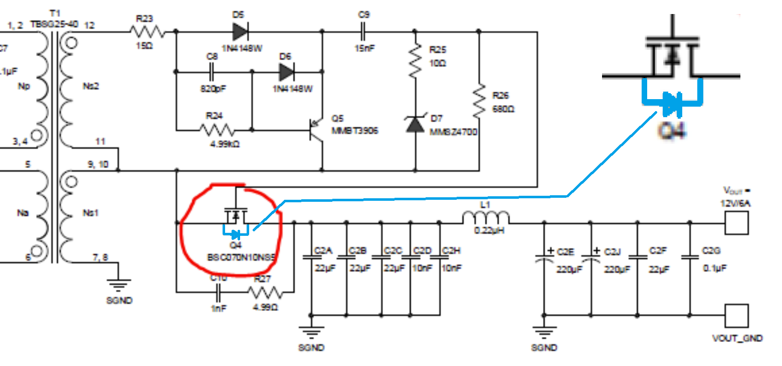
It's acting as a synchronous rectifier. See the body diode I've highlighted in blue: -

enter image description here

ThatBy itself, the blue diode would beis how you would place a regular diode in the circuit. The MOSFET replaces the regular diode and, when expected to conduct, the MOSFET shorts out its own body diode giving lower conduction losses than a regular diode.

It's acting as a synchronous rectifier. See the body diode I've highlighted in blue: -

enter image description here

That blue diode would be how you would place a regular diode in the circuit. The MOSFET replaces the regular diode and, when expected to conduct, the MOSFET shorts out its own body diode giving lower conduction losses.

What's the purpose of the MOSFET on the output of the flyback buck converter in this circuit?

It's acting as a synchronous rectifier. See the body diode I've highlighted in blue: -

enter image description here

By itself, the blue diode is how you would place a regular diode in the circuit. The MOSFET replaces the regular diode and, when expected to conduct, the MOSFET shorts out its own body diode giving lower conduction losses than a regular diode.

Source Link
Andy aka
  • 473.1k
  • 29
  • 383
  • 839

It's acting as a synchronous rectifier. See the body diode I've highlighted in blue: -

enter image description here

That blue diode would be how you would place a regular diode in the circuit. The MOSFET replaces the regular diode and, when expected to conduct, the MOSFET shorts out its own body diode giving lower conduction losses.