added 285 characters in body
Source Link
Andy aka
  • 473.1k
  • 29
  • 383
  • 839

I have tried Window comparator circuit it work fine during water filling from 1V to 5V, but it suddenly start the pump at 4.5V

A window comparator will do this because it doesn't have hysteresis.

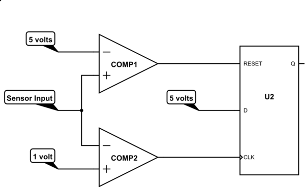
So You need hysteresis between the upper and lower voltage "action" levels. You could use a single comparator with positive feedback to give hysteresis but, try thisthe resistor values can be a little fiddly to calculate so, my preferred approach is to use a dual comparator driving a D type flip-flop with a reset circuit (pretty.

The flip-flop is commonly available) in a single SMD package or dual package: -
schematic

simulate this circuit – Schematic created using CircuitLab

If the sensor output becomes less than 1 volt then, COMP2's output will trigger the flip-flop (via CLK) and, because D is set to logic 1 level, the Q output will be set.

The Q output then drives your pump (via appropriate circuitry) until the sensor output hits 5 volts. At this point COMP1 resets the flip-flop and turns the pump off. When the water level drops sufficiently, COMP2 will re-trigger the flip-flop to restart the pump.

I might be tempted to add some water overflow protection circuit as a back-up against a single failure of the circuit.

I have tried Window comparator circuit it work fine during water filling from 1V to 5V, but it suddenly start the pump at 4.5V

A window comparator will do this because it doesn't have hysteresis.

So, try this dual comparator driving a D type flip-flop with a reset circuit (pretty commonly available): -

schematic

simulate this circuit – Schematic created using CircuitLab

If the sensor output becomes less than 1 volt then, COMP2's output will trigger the flip-flop (via CLK) and, because D is set to logic 1 level, the Q output will be set.

The Q output then drives your pump (via appropriate circuitry) until the sensor output hits 5 volts. At this point COMP1 resets the flip-flop and turns the pump off. When the water level drops sufficiently, COMP2 will re-trigger the flip-flop to restart the pump.

I might be tempted to add some water overflow protection circuit as a back-up against a single failure of the circuit.

I have tried Window comparator circuit it work fine during water filling from 1V to 5V, but it suddenly start the pump at 4.5V

A window comparator will do this because it doesn't have hysteresis. You need hysteresis between the upper and lower voltage "action" levels. You could use a single comparator with positive feedback to give hysteresis but, the resistor values can be a little fiddly to calculate so, my preferred approach is to use a dual comparator driving a D type flip-flop with a reset circuit.

The flip-flop is commonly available in a single SMD package or dual package: -

schematic

simulate this circuit – Schematic created using CircuitLab

If the sensor output becomes less than 1 volt then, COMP2's output will trigger the flip-flop (via CLK) and, because D is set to logic 1 level, the Q output will be set.

The Q output then drives your pump (via appropriate circuitry) until the sensor output hits 5 volts. At this point COMP1 resets the flip-flop and turns the pump off. When the water level drops sufficiently, COMP2 will re-trigger the flip-flop to restart the pump.

I might be tempted to add some water overflow protection circuit as a back-up against a single failure of the circuit.

added 26 characters in body
Source Link
Andy aka
  • 473.1k
  • 29
  • 383
  • 839

I have tried Window comparator circuit it work fine during water filling from 1V to 5V, but it suddenly start the pump at 4.5V

A window comparator will do this because it doesn't have hysteresis.

So, try this dual comparator driving a D type flip-flop with a reset circuit (pretty commonly available): -

schematic

simulate this circuit – Schematic created using CircuitLab

If the sensor output isbecomes less than 1 volt then COMP2, COMP2's output will trigger the flip-flop (via CLK) and, because D is set to logic 1 level, the Q output will be set.

The Q output then drives your pump (via appropriate circuitry) until the sensor output hits 5 volts. At this point COMP1 resets the flip-flop and turns the pump off. When the water level drops sufficiently, COMP2 will re-trigger the flip-flop to restart the pump.

I might be tempted to add some water overflow protection circuit as a back-up against a single failure of the circuit.

I have tried Window comparator circuit it work fine during water filling from 1V to 5V, but it suddenly start the pump at 4.5V

A window comparator will do this because it doesn't have hysteresis.

So, try this dual comparator driving a D type flip-flop with a reset circuit (pretty commonly available): -

schematic

simulate this circuit – Schematic created using CircuitLab

If the sensor output is less than 1 volt then COMP2 will trigger the flip-flop (via CLK) and, because D is set to logic 1 level, the Q output will be set.

Q then drives your pump (via appropriate circuitry) until the sensor output hits 5 volts. At this point COMP1 resets the flip-flop and turns the pump off. When the water level drops sufficiently, COMP2 will re-trigger the flip-flop to restart the pump.

I might be tempted to add some water overflow protection circuit as a back-up against a single failure of the circuit.

I have tried Window comparator circuit it work fine during water filling from 1V to 5V, but it suddenly start the pump at 4.5V

A window comparator will do this because it doesn't have hysteresis.

So, try this dual comparator driving a D type flip-flop with a reset circuit (pretty commonly available): -

schematic

simulate this circuit – Schematic created using CircuitLab

If the sensor output becomes less than 1 volt then, COMP2's output will trigger the flip-flop (via CLK) and, because D is set to logic 1 level, the Q output will be set.

The Q output then drives your pump (via appropriate circuitry) until the sensor output hits 5 volts. At this point COMP1 resets the flip-flop and turns the pump off. When the water level drops sufficiently, COMP2 will re-trigger the flip-flop to restart the pump.

I might be tempted to add some water overflow protection circuit as a back-up against a single failure of the circuit.

Source Link
Andy aka
  • 473.1k
  • 29
  • 383
  • 839

I have tried Window comparator circuit it work fine during water filling from 1V to 5V, but it suddenly start the pump at 4.5V

A window comparator will do this because it doesn't have hysteresis.

So, try this dual comparator driving a D type flip-flop with a reset circuit (pretty commonly available): -

schematic

simulate this circuit – Schematic created using CircuitLab

If the sensor output is less than 1 volt then COMP2 will trigger the flip-flop (via CLK) and, because D is set to logic 1 level, the Q output will be set.

Q then drives your pump (via appropriate circuitry) until the sensor output hits 5 volts. At this point COMP1 resets the flip-flop and turns the pump off. When the water level drops sufficiently, COMP2 will re-trigger the flip-flop to restart the pump.

I might be tempted to add some water overflow protection circuit as a back-up against a single failure of the circuit.