added 44 characters in body
Source Link
Andy aka
  • 473k
  • 29
  • 383
  • 839

Per my observations, there is no current source at the IMON terminal.

Actually there is but you didn't recognize it. You probably accept that CS- will be at a slightly lower voltage than the input side of the shunt resistor (\$R_{SNS}\$) due to load current. Does that make sense so far?

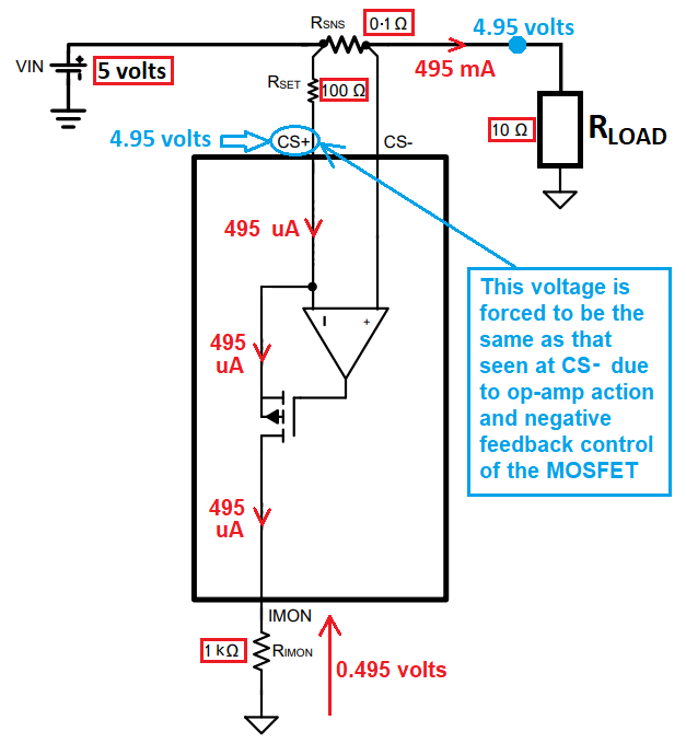
Well, in order to get the op-amp into stability (Cs- = CS+), the voltage at CS+ can be "dragged-down" to equal the voltage at CS- by activating the p-channel MOSFET and taking some current from \$R_{SET}\$, through the MOSFET and down to ground via \$R_{IMON}\$.

Does that make sense and, do you see that this all happens automatically within a negative feedback loop. Hence, the current source at IMON is the op-amp and MOSFET working together.

Of course, that current taken from the CS+ pin flows to ground through \$R_{IMON}\$ and, the voltage produced is proportional to the real load current through the shunt resistor \$R_{SNS}\$.

  • Scaling refers to the current through \$R_{IMON}\$ compared to the actual current through \$R_{SNS}\$.
  • The offset of the op-amp represents an error factor. Ideally it would be 0 μV but nothing ever is that good.

It might help if you concentrated on the crucial parts of the circuit that dictate performance and, put some example numbers on things: -

enter image description hereenter image description here

Per my observations, there is no current source at the IMON terminal.

Actually there is but you didn't recognize it. You probably accept that CS- will be at a slightly lower voltage than the input side of the shunt resistor (\$R_{SNS}\$) due to load current. Does that make sense so far?

Well, in order to get the op-amp into stability (Cs- = CS+), the voltage at CS+ can be "dragged-down" to equal the voltage at CS- by activating the p-channel MOSFET and taking some current from \$R_{SET}\$, through the MOSFET and down to ground via \$R_{IMON}\$.

Does that make sense and, do you see that this all happens automatically within a negative feedback loop. Hence, the current source at IMON is the op-amp and MOSFET working together.

Of course, that current taken from the CS+ pin flows to ground through \$R_{IMON}\$ and, the voltage produced is proportional to the real load current through the shunt resistor \$R_{SNS}\$.

  • Scaling refers to the current through \$R_{IMON}\$ compared to the actual current through \$R_{SNS}\$.
  • The offset of the op-amp represents an error factor. Ideally it would be 0 μV but nothing ever is that good.

It might help if you concentrated on the crucial circuit and put example numbers on things: -

enter image description here

Per my observations, there is no current source at the IMON terminal.

Actually there is but you didn't recognize it. You probably accept that CS- will be at a slightly lower voltage than the input side of the shunt resistor (\$R_{SNS}\$) due to load current. Does that make sense so far?

Well, in order to get the op-amp into stability (Cs- = CS+), the voltage at CS+ can be "dragged-down" to equal the voltage at CS- by activating the p-channel MOSFET and taking some current from \$R_{SET}\$, through the MOSFET and down to ground via \$R_{IMON}\$.

Does that make sense and, do you see that this all happens automatically within a negative feedback loop. Hence, the current source at IMON is the op-amp and MOSFET working together.

Of course, that current taken from the CS+ pin flows to ground through \$R_{IMON}\$ and, the voltage produced is proportional to the real load current through the shunt resistor \$R_{SNS}\$.

  • Scaling refers to the current through \$R_{IMON}\$ compared to the actual current through \$R_{SNS}\$.
  • The offset of the op-amp represents an error factor. Ideally it would be 0 μV but nothing ever is that good.

It might help if you concentrated on the crucial parts of the circuit that dictate performance and, put some example numbers on things: -
enter image description here

deleted 4 characters in body
Source Link
Andy aka
  • 473k
  • 29
  • 383
  • 839

Per my observations, there is no current source at the IMON terminal.

Actually there is but you didn't recognize it. You probably accept that CS- will be at a slightly lower voltage than the input side of the shunt resistor (\$R_{SNS}\$) due to load current. Does that make sense so far?

Well, in order to get the op-amp into stability (Cs- = CS+), the voltage at CS+ can be "dragged-down" to equal the voltage at CS- by activating the p-channel MOSFET and taking some current from \$R_{SET}\$, through the MOSFET and down to ground via \$R_{IMON}\$.

Does that make sense and, do you see that this all happens automatically within a negative feedback loop. Hence, the current source at IMON is the op-amp and MOSFET working together.

Of course, that current taken from the CS+ pin flows to ground through \$R_{IMON}\$ and, the voltage produced is proportional to the real load current through the shunt resistor \$R_{SNS}\$.

  • Scaling refers to the current through \$R_{IMON}\$ compared to the actual current through \$R_{SNS}\$.
  • The offset of the op-amp represents an error factor. Ideally it would be 0 μV but nothing ever is that good.

Maybe itIt might help if you concentrated on the crucial elementscircuit and put someexample numbers on things: -

enter image description here

Per my observations, there is no current source at the IMON terminal.

Actually there is but you didn't recognize it. You probably accept that CS- will be at a slightly lower voltage than the input side of the shunt resistor (\$R_{SNS}\$) due to load current. Does that make sense so far?

Well, in order to get the op-amp into stability (Cs- = CS+), the voltage at CS+ can be "dragged-down" to equal the voltage at CS- by activating the p-channel MOSFET and taking some current from \$R_{SET}\$, through the MOSFET and down to ground via \$R_{IMON}\$.

Does that make sense and, do you see that this all happens automatically within a negative feedback loop. Hence, the current source at IMON is the op-amp and MOSFET working together.

Of course, that current taken from the CS+ pin flows to ground through \$R_{IMON}\$ and, the voltage produced is proportional to the real load current through the shunt resistor \$R_{SNS}\$.

  • Scaling refers to the current through \$R_{IMON}\$ compared to the actual current through \$R_{SNS}\$.
  • The offset of the op-amp represents an error factor. Ideally it would be 0 μV but nothing ever is that good.

Maybe it might help if you concentrated on the crucial elements and put some numbers on things: -

enter image description here

Per my observations, there is no current source at the IMON terminal.

Actually there is but you didn't recognize it. You probably accept that CS- will be at a slightly lower voltage than the input side of the shunt resistor (\$R_{SNS}\$) due to load current. Does that make sense so far?

Well, in order to get the op-amp into stability (Cs- = CS+), the voltage at CS+ can be "dragged-down" to equal the voltage at CS- by activating the p-channel MOSFET and taking some current from \$R_{SET}\$, through the MOSFET and down to ground via \$R_{IMON}\$.

Does that make sense and, do you see that this all happens automatically within a negative feedback loop. Hence, the current source at IMON is the op-amp and MOSFET working together.

Of course, that current taken from the CS+ pin flows to ground through \$R_{IMON}\$ and, the voltage produced is proportional to the real load current through the shunt resistor \$R_{SNS}\$.

  • Scaling refers to the current through \$R_{IMON}\$ compared to the actual current through \$R_{SNS}\$.
  • The offset of the op-amp represents an error factor. Ideally it would be 0 μV but nothing ever is that good.

It might help if you concentrated on the crucial circuit and put example numbers on things: -

enter image description here

added 192 characters in body
Source Link
Andy aka
  • 473k
  • 29
  • 383
  • 839

Per my observations, there is no current source at the IMON terminal.

Actually there is but you didn't recognize it. You probably accept that CS- will be at a slightly lower voltage than the input side of the shunt resistor (\$R_{SNS}\$) due to load current. Does that make sense so far?

Well, in order to get the op-amp into stability (Cs- = CS+), the voltage at CS+ can be "dragged-down" to equal the voltage at CS- by activating the p-channel MOSFET and taking some current from \$R_{SET}\$, through the MOSFET and down to ground via \$R_{IMON}\$.

Does that make sense and, do you see that this all happens automatically within a negative feedback loop. Hence, the current source at IMON is the op-amp and MOSFET working together.

Of course, that current taken from the CS+ pin flows to ground through \$R_{IMON}\$ and, the voltage produced is proportional to the real load current through the shunt resistor \$R_{SNS}\$.

  • Scaling refers to the current through \$R_{IMON}\$ compared to the actual current through \$R_{SNS}\$.
  • The offset of the op-amp represents an error factor. Ideally it would be 0 μV but nothing ever is that good.

Maybe it might help if you concentrated on the crucial elements and put some numbers on things: -

enter image description here

Per my observations, there is no current source at the IMON terminal.

Actually there is but you didn't recognize it. You probably accept that CS- will be at a slightly lower voltage than the input side of the shunt resistor (\$R_{SNS}\$) due to load current. Does that make sense so far?

Well, in order to get the op-amp into stability (Cs- = CS+), the voltage at CS+ can be "dragged-down" to equal the voltage at CS- by activating the p-channel MOSFET and taking some current from \$R_{SET}\$, through the MOSFET and down to ground via \$R_{IMON}\$.

Does that make sense and, do you see that this all happens automatically within a negative feedback loop. Hence, the current source at IMON is the op-amp and MOSFET working together.

Of course, that current taken from the CS+ pin flows to ground through \$R_{IMON}\$ and, the voltage produced is proportional to the real load current through the shunt resistor \$R_{SNS}\$.

  • Scaling refers to the current through \$R_{IMON}\$ compared to the actual current through \$R_{SNS}\$.
  • The offset of the op-amp represents an error factor. Ideally it would be 0 μV but nothing ever is that good.

Maybe it might help if you concentrated on the crucial elements and put some numbers on things: -

enter image description here

Source Link
Andy aka
  • 473k
  • 29
  • 383
  • 839
Loading